Nissan Maxima Service and Repair Manual: Auto light system
System Diagram
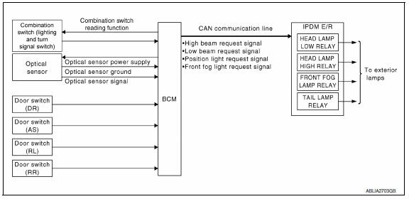
System Description
- BCM (Body Control Module) controls auto light operation according to signals from optical sensor, lighting switch and ignition switch.
- IPDM E/R (Intelligent Power Distribution Module Engine Room) operates parking, license plate, tail, front fog lamps and headlamps according to CAN communication signals from BCM.
- Optical sensor detects ambient brightness of 800 to 2,500 lux, converts light (lux) to voltage, and then sends the optical sensor signal to BCM.
OUTLINE
The auto light control system has an optical sensor that detects outside brightness.
When the lighting switch is in AUTO position, it automatically turns ON/OFF the parking, license plate, tail, front fog lamps and headlamps in accordance with the ambient light. Sensitivity can be adjusted in four steps.
For the details of the setting, refer to EXL-191, "HEADLAMP : CONSULT Function (BCM - HEAD LAMP)".
Component Parts Location
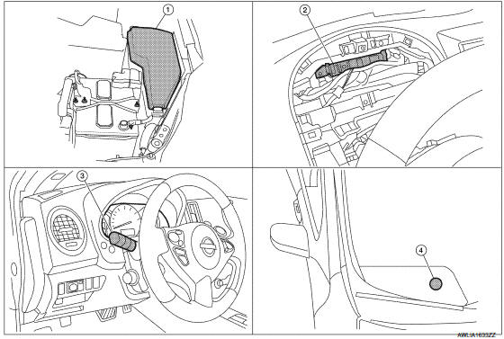
- IPDM E/R E17, E18, E200
- BCM M16, M17, M18, M19, M21 (view with combination meter removed)
- Combination switch (lighting and turn signal switch) M28
- Optical sensor M66
Component Description
AUTO LIGHT OPERATION
Applicable lamps
- Low beam headlamp
- Parking, license plate and tail lamps
- High beam headlamp (with the lighting switch in HIGH BEAM position)
- Front fog lamp (with the lighting switch in front fog lamp ON position)
When the lighting switch is in AUTO position with the ignition switch in ON position, BCM detects the AUTO LIGHT (ON) by BCM combination switch (lighting and turn signal switch) reading function. BCM automatically turns ON/OFF the applicable lamps according to ambient brightness. NOTE: Timing for when lamps turn ON/OFF can be changed by the function setting of CONSULT. Refer to EXL-191, "HEADLAMP : CONSULT Function (BCM - HEAD LAMP)".
 Daytime running light system
System Diagram
System Description
The headlamp system for Canada vehicles is equipped with a daytime light
relay that activates the high beam headlamps at approximately half
illumination whene ...
 Front fog lamp
System Diagram
System Description
BCM (Body Control Module) controls front fog lamp operation.
IPDM E/R (Intelligent Power Distribution Module Engine Room)
operates front fog lamp accordin ...
Other materials:
C1155 BR fluid level low
Description
The brake fluid level switch converts the brake fluid level to an electric
signal and transmits it to the ABS actuator
and electric unit (control unit).
DTC Logic
DTC DETECTION LOGIC
DTC CONFIRMATION PROCEDURE
1.CHECK SELF-DIAGNOSIS RESULTS
Check the self-diagnosis results. ...
Microphone signal circuit
Description
Voice signals are transmitted from the microphone to the Bluetooth control
unit using the microphone signal circuits.
Diagnosis Procedure
1.CHECK HARNESS BETWEEN BLUETOOTH CONTROL UNIT AND MICROPHONE
Turn ignition switch OFF.
Disconnect Bluetooth control unit connector and ...
Drive mode selector
Drive mode selector switches
Two driving modes can be selected by using the
drive mode selector switches, NORMAL and
SPORT.
NOTE:
When the drive mode select switch selects a
mode, the mode may not switch quickly. This
is not a malfunction.
Select the NORMAL mode for normal driving. ...
Nissan Maxima Owners Manual
- Illustrated table of contents
- Safety-Seats, seat belts and supplemental restraint system
- Instruments and controls
- Pre-driving checks and adjustments
- Monitor, climate, audio, phone and voice recognition systems
- Starting and driving
- In case of emergency
- Appearance and care
- Do-it-yourself
- Maintenance and schedules
- Technical and consumer information
Nissan Maxima Service and Repair Manual

0.0075