Nissan Maxima Service and Repair Manual: P1778 step motor
Description
-
The step motor changes the step by turning 4 coils ON/OFF according to the signal from TCM. As a result, the flow of line pressure to primary pulley is changed and pulley ratio is controlled.
-
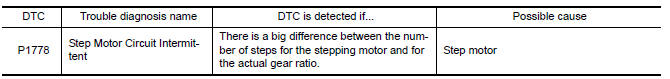
This diagnosis item is detected when the electrical system is OK, but the mechanical system is NG.
-
This diagnosis item is detected when the state of the changing of the speed mechanism in the unit does not operate normally.
DTC Logic
DTC DETECTION LOGIC
DTC CONFIRMATION PROCEDURE
CAUTION:
-
Always drive vehicle at a safe speed.
-
Before starting "DTC CONFIRMATION PROCEDURE", confirm "Hi" or "Mid" or "Low" fixation by "PRI SPEED" and "VEHICLE SPEED" in "Data Monitor".
-
If hi-geared fixation occurred, go to TM-112, "Diagnosis Procedure".
NOTE: Immediately after performing any "DTC CONFIRMATION PROCEDURE", always turn ignition switch OFF.
Then wait at least 10 seconds before performing the next test.
1.CHECK DTC DETECTION
 With CONSULT
-
Turn ignition switch ON.
-
Select "Data Monitor" in "TRANSMISSION".
-
Check that output voltage of CVT fluid temperature sensor is within the range below.
ATF TEMP SEN : 1.0 - 2.0 V
If it is out of range, drive the vehicle to decrease the voltage (warm up the fluid) or stop engine to increase the voltage (cool down the fluid)
4. Start engine and maintain the following conditions for at least 30 consecutive seconds.
Start test from 0 km/h (0 MPH)
Constant acceleration : Keep 30 seconds or more
VEHICLE SPEED : 10 km/h (6 MPH) or more
ACC PEDAL OPEN : More than 1.0/8
RANGE : "D" position
ENG SPEED : 450 rpm or more
 With GST
Follow the procedure "With CONSULT".
Diagnosis Procedure
1.CHECK STEP MOTOR SYSTEM
Check step motor system. Refer to TM-109, "DTC Logic".
2.CHECK PRIMARY SPEED SENSOR SYSTEM
Check primary speed sensor system. Refer to TM-57, "DTC Logic".
3.CHECK SECONDARY SPEED SENSOR SYSTEM
Check secondary speed sensor system. Refer to TM-60, "DTC Logic".
4.DETECT MALFUNCTIONING ITEMS
Check TCM connector pin terminals for damage or loose connection with harness connector.
 P1777 step motor
Description
The step motor changes the step by turning 4 coils ON/OFF
according to the signal from TCM. As a result, the
flow of line pressure to primary pulley is changed and pulley ratio is
c ...
 Shift position indicator circuit
Description
TCM sends position indicator signals to
combination meter via CAN communication line.
The selector lever position is indicated on the
shift position indica ...
Other materials:
Break-in schedule
CAUTION
During the first 1,200 miles (2,000 km),
follow these recommendations to obtain
maximum engine performance and ensure
the future reliability and economy of your
new vehicle. Failure to follow these recommendations
may result in shortened
engine life and reduced engine
performance.
...
Around View Monitor system operation
With the ignition switch in the ON position, move
the shift lever to the R (Reverse) position or press
the CAMERA button to operate the Around
View Monitor.
When the camera is first activated with the bird'seye
view in the display, a red icon (if so equipped)
will flash on the screen. This i ...
Sunroof unit assembly
Inspection and Adjustment
INSPECTION
Wind Deflector
Open glass lid assembly fully.
Visually check for proper installation, damaged/deteriorated
components, or foreign objects within mechanism.
Correct as required for
smooth operation.
Check for grease at the wind deflector arm ( ...
Nissan Maxima Owners Manual
- Illustrated table of contents
- Safety-Seats, seat belts and supplemental restraint system
- Instruments and controls
- Pre-driving checks and adjustments
- Monitor, climate, audio, phone and voice recognition systems
- Starting and driving
- In case of emergency
- Appearance and care
- Do-it-yourself
- Maintenance and schedules
- Technical and consumer information
Nissan Maxima Service and Repair Manual

0.0068