Nissan Maxima Service and Repair Manual: P1777 step motor
Description
The step motor changes the step by turning 4 coils ON/OFF according to the signal from TCM. As a result, the flow of line pressure to primary pulley is changed and pulley ratio is controlled.
DTC Logic
DTC DETECTION LOGIC
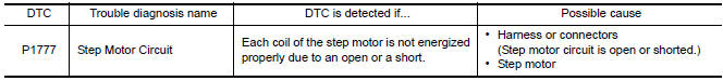
DTC CONFIRMATION PROCEDURE
CAUTION: Always drive vehicle at a safe speed.
NOTE: Immediately after performing any "DTC CONFIRMATION PROCEDURE", always turn ignition switch OFF.
Then wait at least 10 seconds before performing the next test.
1.CHECK DTC DETECTION
 With CONSULT
-
Start engine.
-
Drive vehicle for at least 5 consecutive seconds.
-
Perform "Self Diagnostic Results" in "TRANSMISSION".
 With GST
Follow the procedure "With CONSULT".
Diagnosis Procedure
Regarding Wiring Diagram information, refer to TM-126, "Wiring Diagram".
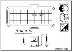
1.CHECK STEP MOTOR CIRCUIT
-
Turn ignition switch OFF.
-
Disconnect TCM connector.
-
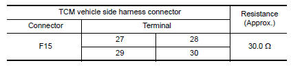
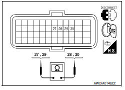
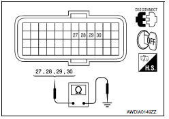
Check resistance between TCM vehicle side harness connector terminals.
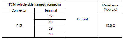
4. Check resistance between TCM vehicle side harness connector terminals and ground.
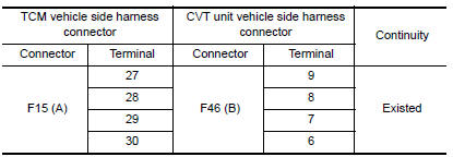
2.CHECK HARNESS BETWEEN TCM AND CVT UNIT (STEP MOTOR) (PART 1)
-
Disconnect CVT unit connector.
-
Check continuity between TCM vehicle side harness connector terminals and CVT unit vehicle side harness connector terminals.
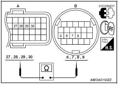
3.CHECK HARNESS BETWEEN TCM AND CVT UNIT (STEP MOTOR) (PART 2)
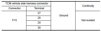
Check continuity between TCM vehicle side harness connector terminals and ground.
4.CHECK STEP MOTOR
Check step motor. Refer to TM-111, "Component Inspection (Step Motor)".
5.DETECT MALFUNCTIONING ITEMS
Check TCM connector pin terminals for damage or loose connection with harness connector.
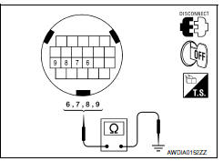
Component Inspection (Step Motor)
1.CHECK STEP MOTOR
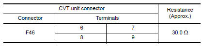
1. Check resistance between CVT unit connector terminals.
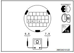
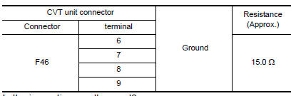
2. Check resistance between CVT unit connector terminals and ground.
 P1745 line pressure control
Description
The line pressure solenoid valve regulates the oil pump
discharge pressure to suit the driving condition in
response to a signal sent from the TCM.
DTC Logic
DTC DETECTION LOGIC
...
 P1778 step motor
Description
The step motor changes the step by turning 4
coils ON/OFF according to the signal from TCM. As a result,
the flow of line pressure to primary pulley is changed and pulle ...
Other materials:
P0740 torque converter
Description
The torque converter clutch solenoid valve is activated by the TCM
in response to signals sent from the vehicle
speed and accelerator pedal position sensors. Lock-up piston operation will
then be controlled.
Lock-up operation, however, is prohibited when CVT fl ...
Engine coolant temperature gauge
The gauge indicates the engine coolant temperature.
The engine coolant temperature is within the
normal range 1 when the gauge needle points
within the zone shown in the illustration.
The engine coolant temperature varies with the
outside air temperature and driving conditions.
CAUTION ...
ICC system limitations
WARNING
Listed below are the system limitations for
the ICC system. Failure to operate the
vehicle in accordance with these system
limitations could result in serious injury or
death.
The ICC system is primarily intended for
use on straight, dry, open roads with
light traffic. It is ...
Nissan Maxima Owners Manual
- Illustrated table of contents
- Safety-Seats, seat belts and supplemental restraint system
- Instruments and controls
- Pre-driving checks and adjustments
- Monitor, climate, audio, phone and voice recognition systems
- Starting and driving
- In case of emergency
- Appearance and care
- Do-it-yourself
- Maintenance and schedules
- Technical and consumer information
Nissan Maxima Service and Repair Manual

0.011