Nissan Maxima Service and Repair Manual: P2122, P2123 APP sensor
Description
The accelerator pedal position sensor is installed on the upper end of the accelerator pedal assembly. The sensor detects the accelerator position and sends a signal to the ECM.
Accelerator pedal position sensor has two sensors. These sensors are a kind of potentiometer which transform the accelerator pedal position into output voltage, and emit the voltage signal to the ECM.
In addition, these sensors sends opening and closing speed of the accelerator pedal and feed the voltage signals to the ECM. The ECM judges the current opening angle of the accelerator pedal from these signals and controls the throttle control motor based on these signals.
Idle position of the accelerator pedal is determined by the ECM receiving the signal from the accelerator pedal position sensor. The ECM uses this signal for engine operations such as fuel cut.
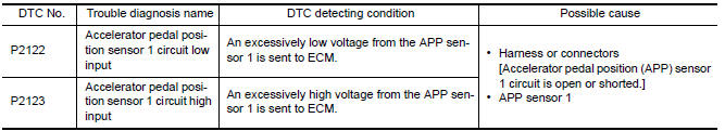
DTC Logic
DTC DETECTION LOGIC
NOTE: If DTC P2122 or P2123 is displayed with DTC P0643, first perform the trouble diagnosis for DTC P0643.
Refer to EC-394, "DTC Logic".
DTC CONFIRMATION PROCEDURE
1.PRECONDITIONING
If DTC Confirmation Procedure has been previously conducted, always perform the following before conducting the next test.
- Turn ignition switch OFF and wait at least 10 seconds.
- Turn ignition switch ON.
- Turn ignition switch OFF and wait at least 10 seconds.
TESTING CONDITION: Before performing the following procedure, confirm that battery voltage is more than 8 V at idle
2.PERFORM DTC CONFIRMATION PROCEDURE
- Start engine and let it idle for 1 second.
- Check DTC.
Diagnosis Procedure
1.CHECK GROUND CONNECTION
- Turn ignition switch OFF.
- Check ground connection E9.
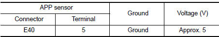
2.CHECK APP SENSOR 1 POWER SUPPLY CIRCUIT
- Disconnect accelerator pedal position (APP) sensor harness connector.
- Turn ignition switch ON.
- Check the voltage between APP sensor harness connector and ground.
3.CHECK APP SENSOR 1 GROUND CIRCUIT FOR OPEN AND SHORT
- Turn ignition switch OFF.
- Disconnect ECM harness connector.
- Check the continuity between APP sensor harness connector and ECM harness connector.
- Also check harness for short to ground and short to power.
Is the
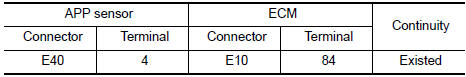
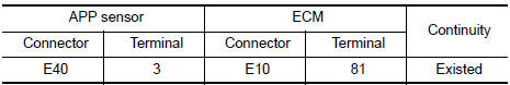
4.CHECK APP SENSOR INPUT SIGNAL CIRCUIT FOR OPEN AND SHORT
- Check the continuity between APP sensor harness connector and ECM harness connector
- Also check harness for short to ground and short to power.
5.CHECK APP SENSOR
6.REPLACE ACCELERATOR PEDAL ASSEMBLY
- Replace accelerator pedal assembly.
7.CHECK INTERMITTENT INCIDENT
Component Inspection
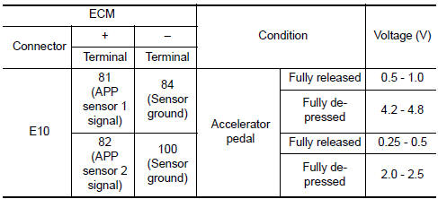
1.CHECK ACCELERATOR PEDAL POSITION SENSOR
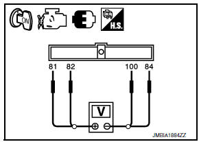
- Reconnect all harness connectors disconnected.
- Turn ignition switch ON.
- Check the voltage between ECM harness connector terminals under the following conditions.
2.REPLACE ACCELERATOR PEDAL ASSEMBLY
- Replace accelerator pedal assembly.
Special Repair Requirement
1.PERFORM ACCELERATOR PEDAL RELEASED POSITION LEARNING
2.PERFORM THROTTLE VALVE CLOSED POSITION LEARNING
3.PERFORM IDLE AIR VOLUME LEARNING
 P2119 electric throttle control actuator
Description
Electric throttle control actuator consists of throttle control motor,
throttle position sensor, etc.
The throttle control motor is operated by the ECM and it opens and closes the
...
 P2127, P2128 APP sensor
Description
The accelerator pedal position sensor is installed on the upper end
of the accelerator pedal assembly. The sensor detects the accelerator
position and sends a signal to the ECM.
...
Other materials:
Fuel recommendation
NISSAN recommends the use of unleaded premium
gasoline with an octane rating of at least
91 AKI (Anti-Knock Index) number (Research
octane number 96). If unleaded premium gasoline
is not available, you may use unleaded regular
gasoline with an octane rating of at least 87 AKI
number (Research ...
Precaution
PRECAUTIONS
Precaution for Supplemental Restraint System (SRS) "AIR
BAG" and "SEAT BELT
PRE-TENSIONER"
The Supplemental Restraint System such as "AIR BAG" and
"SEAT BELT PRE-TENSIONER", used along
with a front seat belt, helps to reduce the risk or severity of injury to the
driver and fr ...
Wiring diagram
MONOCHROME DISPLAY
Wiring Diagram - With BOSE Audio System
...
Nissan Maxima Owners Manual
- Illustrated table of contents
- Safety-Seats, seat belts and supplemental restraint system
- Instruments and controls
- Pre-driving checks and adjustments
- Monitor, climate, audio, phone and voice recognition systems
- Starting and driving
- In case of emergency
- Appearance and care
- Do-it-yourself
- Maintenance and schedules
- Technical and consumer information
Nissan Maxima Service and Repair Manual

0.0076