Nissan Maxima Service and Repair Manual: IPDM E/R (intelligent power distribution module engine room)
Reference Value
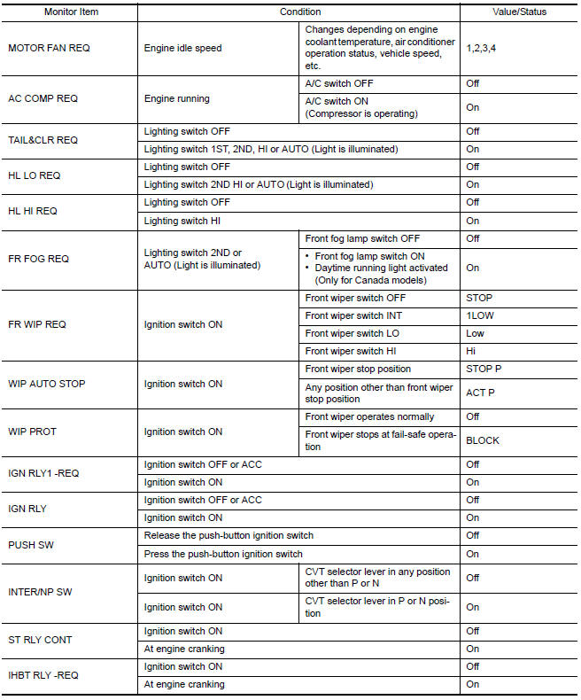
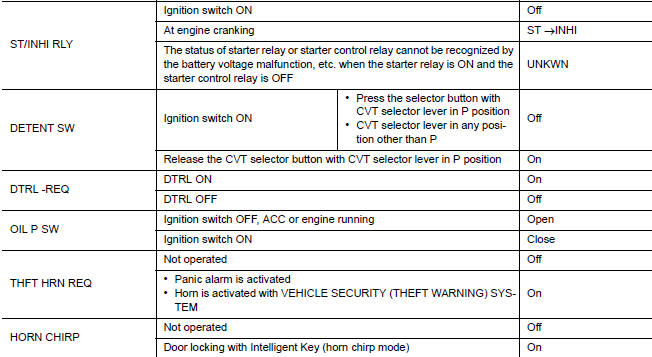
VALUES ON THE DIAGNOSIS TOOL
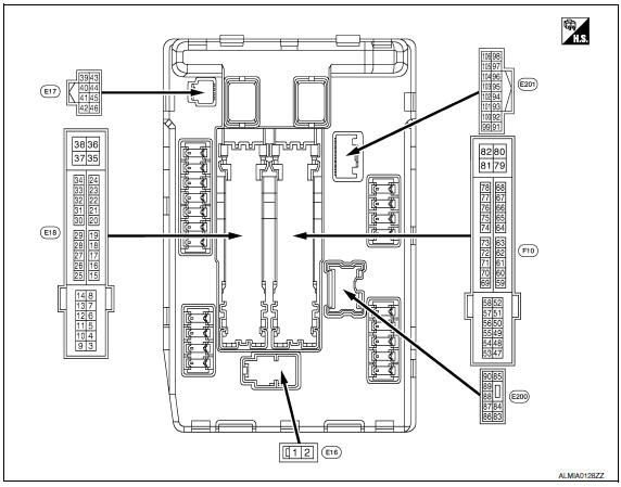
TERMINAL LAYOUT
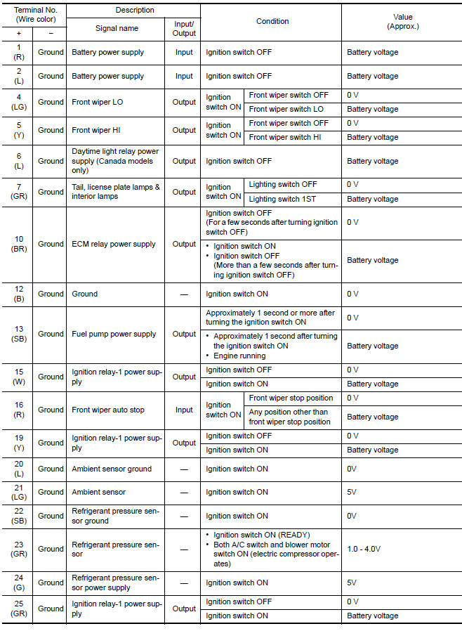
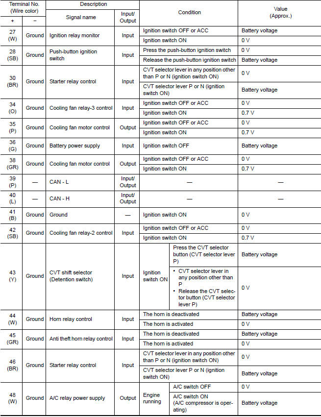
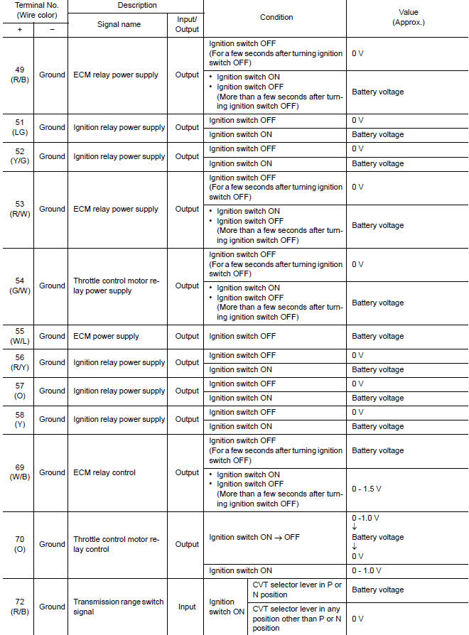
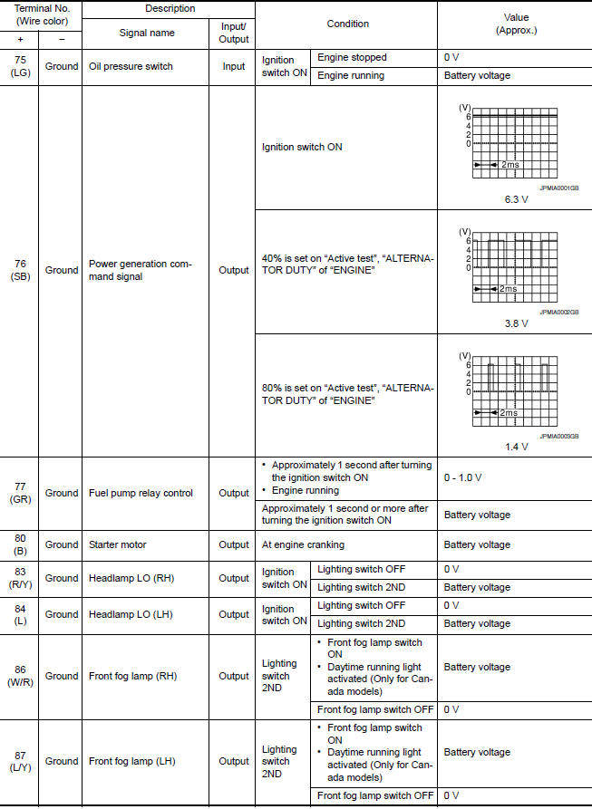
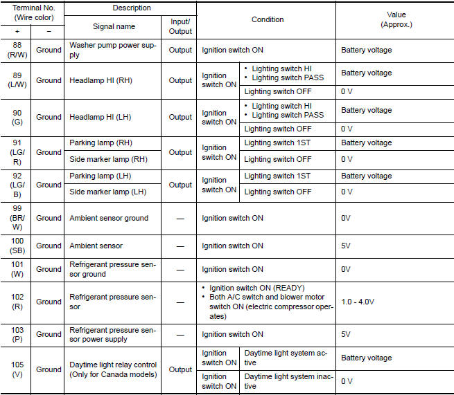
PHYSICAL VALUES
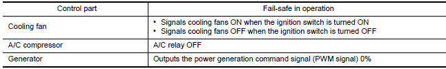
Fail Safe
CAN COMMUNICATION CONTROL
When CAN communication with ECM and BCM is impossible, IPDM E/R performs fail-safe control. After CAN communication recovers normally, it also returns to normal control.
If No CAN Communication Is Available With EC
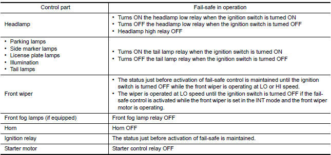
If No CAN Communication Is Available With BCM
IGNITION RELAY MALFUNCTION DETECTION FUNCTION
- IPDM E/R monitors the voltage at the contact circuit and excitation coil circuit of the ignition relay-1 inside it
- IPDM E/R judges the ignition relay-1 error if the voltage differs between the contact circuit and the excitation coil circuit.
- If the ignition relay-1 cannot turn OFF due to contact seizure, it activates the tail lamp relay for 10 minutes to alert the user to the ignition relay-1 malfunction when the ignition switch is turned OFF.
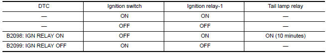
NOTE: The tail lamp turns OFF when the ignition switch is turned ON.
FRONT WIPER CONTROL
IPDM E/R detects front wiper stop position by a front wiper auto stop signal.
When a front wiper auto stop signal is in the conditions listed below, IPDM E/R stops power supply to wiper after repeating a front wiper 10 seconds activation and 20 seconds stop five ti
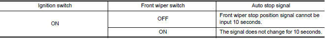
NOTE: This operation status can be confirmed on the IPDM E/R "Data Monitor" that displays "BLOCK" for the item "WIP PROT" while the wiper is stopped.
STARTER MOTOR PROTECTION FUNCTION
IPDM E/R turns OFF the starter control relay to protect the starter motor when the starter control relay remains active for 90 second
DTC Index
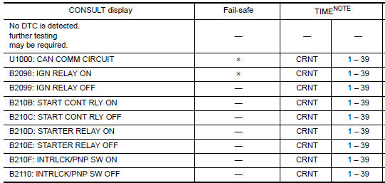
NOTE: The details of TIME display are as follows.
- CRNT: The malfunctions that are detected now
- 1 - 39: The number is indicated when it is normal at present and a malfunction was detected in the past. It increases like 0 → 1 → 2 ··* 38 → 39 after returning to the normal condition whenever IGN OFF → ON. It is fixed to 39 until the self-diagnosis results are erased if it is over 39. It returns to 0 when a malfunction is detected again in the process.
 BCM (body control module)
Reference Value
NOTE: The Signal Tech II Tool (J-50190) can
be used to perform the following functions. Refer to the Signal Tech II User
Guide for additional information.
Activate and display ...
 Wiring diagram
...
Other materials:
Audio antenna
Location of Antenna
AV control unit
AV control unit antenna feeder
In-line connectors M103, M501
Antenna amp.
Window antenna
Satellite radio antenna feeder
Satellite radio antenna
Window Antenna Repair
ELEMENT CHECK
Attach probe circuit tester (ohm setting) to antenna ...
Chassis and Body Maintenance
Brake lines and cables:
Visually inspect for proper installation. Check for
chafing, cracks, deterioration, and signs of leaking.
Replace any deteriorated or damaged parts
immediately.
Brake pads, rotors, drums and linings:
Check for wear, deterioration and fluid leaks.
Replace any deteri ...
RearView Monitor (if so equipped)
1. CAMERA button
WARNING
Failure to follow the warnings and instructions
for proper use of the Rear-
View Monitor system could result in serious
injury or death.
RearView Monitor is a convenience feature
and is not a substitute for proper
backing. Always turn and look out the
...
Nissan Maxima Owners Manual
- Illustrated table of contents
- Safety-Seats, seat belts and supplemental restraint system
- Instruments and controls
- Pre-driving checks and adjustments
- Monitor, climate, audio, phone and voice recognition systems
- Starting and driving
- In case of emergency
- Appearance and care
- Do-it-yourself
- Maintenance and schedules
- Technical and consumer information
Nissan Maxima Service and Repair Manual

0.0057