Nissan Maxima Service and Repair Manual: Rocker Cover
Exploded View
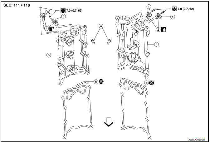
- Camshaft position sensors (LH)
- O-rings
- Camshaft position sensors (RH)
- O-rings
- Rocker cover (RH)
- Rocker cover gasket (RH)
- Rocker cover gasket (LH)
- Rocker cover (LH)
- Refer to INSTALLATION
 Front
Front
Removal and Installation (LH)
REMOVAL
- Remove the engine room cover. Refer to EM-23, "Removal and Installation".
- Remove front air duct. Refer to EM-24, "Removal and Installation".
- Remove blow by hose from rocker cover.
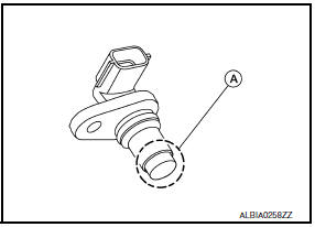
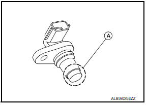
- Remove camshaft position sensors.
CAUTION:
- Handle carefully to avoid dropping and shocks.
- Do not disassemble.
- Do not allow metal powder to adhere to magnetic part at sensor tip (A).
- Do not place sensors in a location where they are exposed to magnetism.
- Remove the ignition coils. Refer to EM-42, "Removal and Installation (LH)".
CAUTION: Do not shock ignition coils.
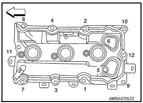
- Remove (LH) rocker cover bolts from cylinder head in the reverse order as shown.
 : Engine front
- Remove the rocker cover and gasket.
INSTALLATION
Installation is in the reverse order of removal.
CAUTION: Do not reuse rocker cover gasket.
- Apply sealant to the areas on the front corners using Tool.
- Use Genuine Silicone RTV Sealant or equivalent. Refer to GI-21, "Recommended Chemical Products and Sealants".

Tool number : WS39930000 ( - )
CAUTION:
- Installation should be done within 5 minutes after applying liquid gasket.
- Do not fill the engine with oil for at least 30 minutes after the components are installed to allow the sealant to cure.
- Tighten the rocker cover bolts in two steps in the order shown.
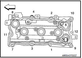
 : Engine front
Rocker cover bolts
Step 1 : 1.96 N*m (0.20 kg-m, 17 in-lb)
Step 2 : 8.33 N*m (0.85 kg-m, 74
in-lb)
Removal and Installation (RH)
REMOVAL
- Remove the engine room cover. Refer to EM-23, "Removal and Installation".
- Remove the front air duct and air duct hose and resonator assembly. Refer to EM-24, "Removal and Installation".
- Remove the intake manifold collector. Refer to EM-28, "Removal and
Installation".
4. Remove ignition coils. Refer to EM-42, "Removal and Installation (RH)". CAUTION: Do not shock ignition coils.
- Remove camshaft position sensors.
CAUTION:
- Handle carefully to avoid dropping and shocks.
- Do not disassemble.
- Do not allow metal powder to adhere to magnetic part at sensor tip (A).
- Do not place sensors in a location where they are exposed to magnetism.
- Remove RH rocker cover bolts from cylinder head in the reverse order as shown.
 : Engine front
- Remove the rocker cover and gasket.
INSTALLATION
Installation is in the reverse order of removal.
CAUTION: Do not reuse gaskets.
- Apply sealant to the areas on the front corners using Tool.
- Use Genuine Silicone RTV Sealant or equivalent. Refer to GI-21, "Recommended Chemical Products and Sealants".
Tool number : WS39930000 ( - )
CAUTION:
- Installation should be done within 5 minutes after applying liquid gasket.
- Do not fill the engine with oil for at least 30 minutes after the components are installed to allow the sealant to cur
- Tighten the rocker cover bolts in two steps in the order shown.
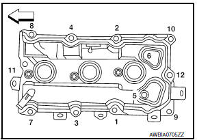
 : Engine front
Rocker cover bolts
Step 1 : 1.96 N*m (0.20 kg-m, 17 in-lb)
Step 2 : 8.33 N*m (0.85 kg-m, 74
in-lb)
 Fuel Injector And Fuel Tube
Exploded View
Fuel feed hose
Quick connector cap
Fuel tube
O-ring
Fuel damper
Fuel damper cap
Clip
O-ring (black)
Fuel injector
O-ring (green)
Refer to INSTALLATI ...
 Intake Valve Timing Control
Exploded View
Intake valve timing control solenoid valve cover gasket (LH)
Intake valve timing control solenoid valve cover gasket (RH)
Intake valve timing control solenoid valve cover (RH) ...
Other materials:
Rear view monitor system
System Diagram
System Description
When the shift selector is in the R position, the display shows a view to the
rear of the vehicle. Lines which indicate the vehicle clearance and distances
are also displayed.
Component Parts Location
Tweeter LH M51
Center speaker M130
Tweeter ...
Rear door speaker
Description
The AV control unit sends audio signals to the BOSE speaker amp. The BOSE
speaker amp. amplifies the
audio signals before sending them to the rear door speakers using the audio
signal circuits.
Diagnosis Procedure
1.CONNECTOR CHECK
Check the AV control unit, BOSE speaker amp. a ...
Remote Engine Start
The button will be on the NISSAN
Intelligent
Key if the vehicle has remote engine start.
This feature allows the engine to start from outside
the vehicle.
The following features may be affected when the
remote start feature is used:
Vehicles with an automatic climate control
sys ...
Nissan Maxima Owners Manual
- Illustrated table of contents
- Safety-Seats, seat belts and supplemental restraint system
- Instruments and controls
- Pre-driving checks and adjustments
- Monitor, climate, audio, phone and voice recognition systems
- Starting and driving
- In case of emergency
- Appearance and care
- Do-it-yourself
- Maintenance and schedules
- Technical and consumer information
Nissan Maxima Service and Repair Manual

0.0057