Nissan Maxima Service and Repair Manual: Rear door speaker
Description
The audio unit sends audio signals to the BOSE speaker amp. The BOSE speaker amp. amplifies the audio signals before sending them to the rear door speakers using the audio signal circuits.
Diagnosis Procedure
1.CONNECTOR CHECK
Check the audio unit, BOSE speaker amp. and speaker connectors for the following:
- Proper connection
- Damage
- Disconnected or loose terminals
2.HARNESS CHECK
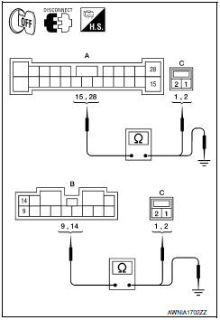
- Disconnect BOSE speaker amp. connectors B109, B110 and suspect speaker connector.
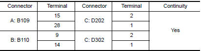
- Check continuity between BOSE speaker amp. harness connectors B109 (A) and B110 (B) and suspect speaker harness connector (C).
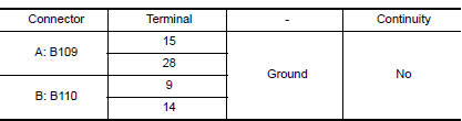
- Check continuity between BOSE speaker amp. harness connectors B109 (A) and B110 (B) and ground.
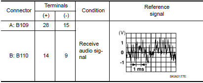
3.REAR DOOR SPEAKER SIGNAL CHECK
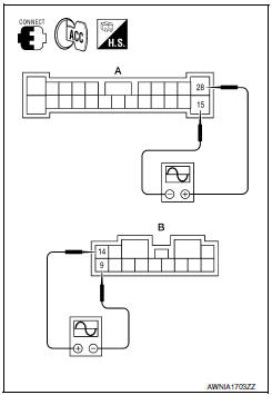
- Connect BOSE speaker amp. connectors and suspect speaker connector.
- Turn ignition switch to ACC.
- Push POWER switch.
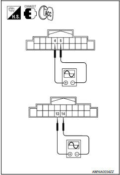
- Check the signal between BOSE speaker amp. harness connectors B109 (A) and B110 (B) terminals with CONSULT or oscilloscope.
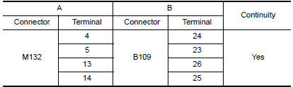
4.HARNESS CHECK
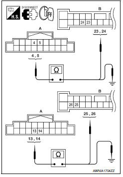
- Disconnect audio unit connector M132 and BOSE speaker amp.
connector B109.
- Check continuity between audio unit harness connector M132 (A) and BOSE speaker amp. harness connector B109 (B).
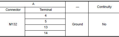
- Check continuity between audio unit harness connector M132 (A) and ground.
5.REAR DOOR SPEAKER SIGNAL CHECK
- Connect audio unit connector M132 and BOSE speaker amp.
connector B109.
- Turn ignition switch to ACC.
- Push POWER switch.
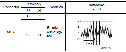
- Check the signal between audio unit harness connector terminals with CONSULT or oscilloscope.
 Center speaker
Description
The audio unit sends audio signals to the BOSE speaker amp. The BOSE speaker
amp. amplifies the audio signals before sending them to the center speaker
using the audio signal circuits ...
 Subwoofer
Description
The audio unit sends audio signals to the BOSE speaker amp. The BOSE speaker
amp. amplifies the audio signals before sending them to the subwoofers using
the audio signal circuits.
D ...
Other materials:
P0451 evap control system pressure sensor
Description
The EVAP control system pressure sensor detects pressure in the
purge line. The sensor output voltage to the ECM increases as pressure
increases
DTC Logic
DTC DETECTION LOGIC
DTC CONFIRMATION PROCEDURE
NOTE:
Never remove fuel filler cap during DTC confirmation procedur ...
RGB synchronizing signal circuit
Description
Transmit the RGB synchronizing signal to the display unit so as to
synchronize the RGB image displayed with
AV control unit.
Diagnosis Procedure
1.CHECK CONTINUITY RGB SYNCHRONIZING SIGNAL CIRCUIT
Turn ignition switch OFF.
Disconnect display unit connector M141 and AV co ...
P1615 diffrence of key
Description
Performs ID verification through BCM and Intelligent Key
when push-button ignition switch is pressed.
Prohibits the start of engine when an unregistered ID of Intelligent Key is
used.
DTC Logic
DTC DETECTION LOGIC
DTC CONFIRMATION PROCEDURE
1.PERFORM DTC CONFIRMATION PROCED ...
Nissan Maxima Owners Manual
- Illustrated table of contents
- Safety-Seats, seat belts and supplemental restraint system
- Instruments and controls
- Pre-driving checks and adjustments
- Monitor, climate, audio, phone and voice recognition systems
- Starting and driving
- In case of emergency
- Appearance and care
- Do-it-yourself
- Maintenance and schedules
- Technical and consumer information
Nissan Maxima Service and Repair Manual

0.0064