Nissan Maxima Service and Repair Manual: Bluetooth control unit
Reference Value
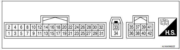
TERMINAL LAYOUT
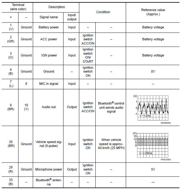
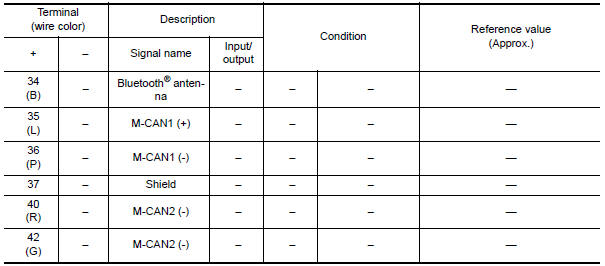
PHYSICAL VALUES
 Satellite radio tuner
Reference Value
PHYSICAL VALUES
...
 Wiring diagram
COLOR DISPLAY
Wiring Diagram - With BOSE Audio system Without Navigation System
...
Other materials:
Key slot
Diagnosis Procedure
Regarding Wiring Diagram information, refer to SEC-147,
"Wiring Diagram" or SEC-128, "Wiring Diagram".
1.CHECK KEY SLOT POWER SUPPLY CIRCUIT
Turn ignition switch OFF.
Disconnect key slot connector.
Check voltage between slot harness co ...
P1572 ASCD brake switch
Description
When the brake pedal is depressed, ASCD brake switch is turned OFF and stop
lamp switch is turned ON.
ECM detects the state of the brake pedal by those two types of input (ON/OFF
signal).
Refer to EC-68, "System Diagram" for the ASCD function.
DTC Logic
DTC DETECTI ...
The low washer fluid warning continues displaying, or does not display
Description
The warning is still displayed even after
washer fluid is added.
The warning is not displayed even though the
washer tank is empty.
Diagnosis Procedure
1.CHECK WASHER FLUID LEVEL SWITCH SIGNAL CIRCUIT
Check the washer fluid level switch signal cir ...
Nissan Maxima Owners Manual
- Illustrated table of contents
- Safety-Seats, seat belts and supplemental restraint system
- Instruments and controls
- Pre-driving checks and adjustments
- Monitor, climate, audio, phone and voice recognition systems
- Starting and driving
- In case of emergency
- Appearance and care
- Do-it-yourself
- Maintenance and schedules
- Technical and consumer information
Nissan Maxima Service and Repair Manual

0.0056