Nissan Maxima Service and Repair Manual: VDC
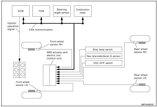
System Diagram
Hydraulic Circuit Diagram
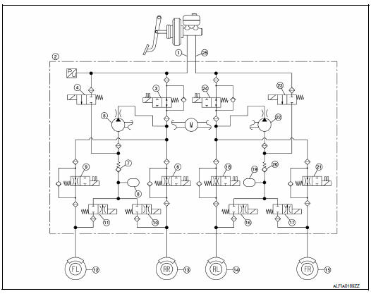
- Primary side
- VDC/TCS/ABS actuator
- Primary side VDC switch-over valve 1 (USV1)
- Primary side VDC switch-over valve 1 (HSV1)
- Primary side pump
- Rear right inlet solenoid valve
- Primary side inlet valve
- Primary side damper
- Front left inlet solenoid valve
- Rear right outlet solenoid valve
- Front left outlet solenoid valve
- Front left caliper
- Rear right caliper
- Rear left caliper
- Front right caliper
- Rear left outlet solenoid valve
- Front right outlet solenoid valve
- Rear left inlet solenoid valve
- Secondary side damper
- Secondary side inlet valve
- Front right inlet solenoid valve
- Secondary side pump
- Secondary side VDC switch-over valve 2 (HSV2)
- Secondary side VDC switch-over valve 2 (USV2)
- Secondary side
System Description
- Vehicle dynamic control system detects driver's steering operation
amount from the steering angle sensor.
Using input information from the yaw rate/side/decel G sensor and wheel speed sensors, the VDC system judges driving conditions (conditions of understeer and oversteer) and controls engine output and brake application to improve vehicle driving stability.
- During VDC operation, it informs driver of system operation by flashing SLIP indicator lamp.
- Electrical system diagnosis by CONSULT is available.
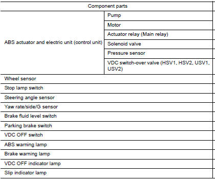
Component Parts Location
- Front wheel sensor LH E19 Front wheel sensor RH E41
- Brake fluid level switch E24
- Parking brake switch E35
- Stop lamp switch E38
- VDC OFF switch M72
- Combination meter M24
- Rear wheel sensor LH C1 Rear wheel sensor RH C2
- Yaw rate/side/decel G sensor M55
- Steering angle sensor M53 (view with steering wheel removed)
- ABS actuator and electric unit (control unit) E26
Component Description

 TCS
TCS
System Diagram
System Description
Traction Control System is a function that electronically controls
engine torque and brake fluid pressure to
ensure the optimum slippage ratio at drive ...
Other materials:
Main line between hvac and ABS circuit
Diagnosis Procedure
1.CHECK CONNECTOR
Turn the ignition switch OFF.
Disconnect the battery cable from the negative
terminal.
Check the following terminals and connectors for
damage, bend and loose connection (connector side
and harness side).
Harness connec ...
Door lock function
DOOR LOCK AND UNLOCK SWITCH
DOOR LOCK AND UNLOCK SWITCH : System Diagram
DOOR LOCK AND UNLOCK SWITCH : System Description
DOOR LOCK FUNCTION
Functions Available by Operating the Door Lock and Unlock Switches on
Driver Door and Passenger Door
Interlocked with the locking operation o ...
Basic inspection
DIAGNOSIS AND REPAIR WORK FLOW
Work Flow
OVERALL SEQUENCE
DETAILED FLOW
1.GET INFORMATION FOR SYMPTOM
Get detailed information from the customer about the symptom (the condition
and the environment when the
incident/malfunction occurred).
2.CONFIRM THE SYMPTOM
Try to confirm the sympt ...
Nissan Maxima Owners Manual
- Illustrated table of contents
- Safety-Seats, seat belts and supplemental restraint system
- Instruments and controls
- Pre-driving checks and adjustments
- Monitor, climate, audio, phone and voice recognition systems
- Starting and driving
- In case of emergency
- Appearance and care
- Do-it-yourself
- Maintenance and schedules
- Technical and consumer information
Nissan Maxima Service and Repair Manual

0.0057