Nissan Maxima Service and Repair Manual: Secondary speed sensor
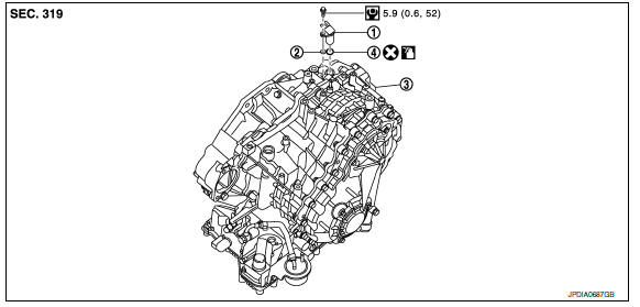
Exploded View
-
Secondary speed sensor
-
Shim
-
Transaxle assembly
-
O-ring
 Apply CVT Fluid NS-2
Removal and Installation
REMOVAL
-
Disconnect the battery negative terminal. Refer to PG-67, "Removal and Installation (Battery)".
-
Remove hoodledge cover (LH).
-
Remove engine room cover.
-
Remove front air duct. Refer to EM-24, "Removal and Installation".
-
Remove air cleaner case assembly. Refer to EM-24, "Removal and Installation"
-
Disconnect secondary speed sensor harness connector.
-
Remove secondary speed sensor (1) and shim (2).
CAUTION: Do not lose the shim.
-
Remove O-ring (3) from secondary speed sensor.
CAUTION: Do not reuse O-ring.
INSTALLATION
Installation is in the reverse order of removal.
CAUTION:
-
Do not reuse O-ring.
-
Apply CVT fluid to O-ring.
Inspection
Check for CVT fluid leakage and check CVT fluid level. Refer to TM-155, "Inspection".
 Control valve
Exploded View
Transaxle assembly
Control valve
Snap ring
Collar
Manual plate
Lock nut
Lock nut
...
 Differential side oil seal
Exploded View
RH differential side oil seal
LH differential side oil seal
Transaxle assembly
Apply CVT Fluid NS-2
Removal and Installation
REMOVAL ...
Other materials:
Parking brake
WARNING
Be sure the parking brake is fully released
before driving. Failure to do so
can cause brake failure and lead to an
accident.
Do not release the parking brake from
outside the vehicle.
Do not use the shift lever in place of the
parking brake. When parking, be sure
the par ...
Warning lights
For additional information on warnings and indicators,
refer to "Vehicle information display" in
this section.
Anti-lock Braking
System (ABS)
warning light
When the ignition switch is placed in the ON
position, the ABS warning light illuminates and
then turns off. This indicates the ABS is o ...
B210F transmission range switch
Description
IPDM E/R confirms the shift position with the following
signals.
Transmission range switch
Shift position signal from BCM (CAN)
DTC Logic
DTC DETECTION LOGIC
NOTE:
If DTC B210F is displayed with DTC
U1000, first perform the trouble diagnosi ...
Nissan Maxima Owners Manual
- Illustrated table of contents
- Safety-Seats, seat belts and supplemental restraint system
- Instruments and controls
- Pre-driving checks and adjustments
- Monitor, climate, audio, phone and voice recognition systems
- Starting and driving
- In case of emergency
- Appearance and care
- Do-it-yourself
- Maintenance and schedules
- Technical and consumer information
Nissan Maxima Service and Repair Manual

0.0064