Nissan Maxima Owners Manual: System maintenance
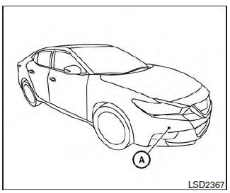
The sensor for the ICC system A is located on the front of the vehicle.
To keep the ICC system operating properly, be sure to observe the following:
- Always keep the sensor area clean.
- Do not strike or damage the areas around the sensor. Do not touch or remove the screw located on the sensor. Doing so could cause a failure or malfunction. If the sensor is damaged due to an accident, it is recommended that you visit a NISSAN dealer.
- Do not attach a sticker (including transparent material) or install an accessory near the sensor. This could cause failure or malfunction.
- Do not attach metallic objects near the sensor area (brush guard, etc.) This could cause failure or malfunction.
- Do not alter, remove, or paint the front bumper.
Before customizing or restoring the front bumper, it is recommended that you visit a NISSAN dealer.
Radio frequency statement
FCC Notice
For USA
This device complies with part 15 of the FCC Rules.
Operation is subject to the following two conditions:
1. This device may not cause harmful interference, and
2. This device must accept any interference received, including interference that may cause undesired operation.
FCC Warning
Changes or modifications not expressly approved by the party responsible for compliance could void the user's authority to operate the equipment.
This equipment has been tested and found to comply with the limits for a Class A digital device, pursuant to Part 15 of the FCC Rules. These limits are designed to provide reasonable protection against harmful interference when the equipment is operated in a commercial environment.
This equipment generates, uses, and can radiate radio frequency energy and, if not installed and used in accordance with the instruction manual, may cause harmful interference to radio communication.
Operation of this equipment in a residential area is likely to cause harmful interference in which case the user will be required to correct the interference at his own expense.
Radio Frequency Radiation Exposure Information: This equipment complies with FCC radiation exposure limits set forth for an uncontrolled environment.
This equipment should be installed and operated with minimum distance of 20 cm between the radiator and your body.
The transmitter must not be co-located or operating in conjunction with any other antenna or transmitter.
For Canada
This device complies with Industry Canada license-exempt RSS standard(s). Operation is subject to the following two conditions: 1. This device may not cause interference, and 2. This device must accept any interference, including interference that may cause undesired operation of the device.
 System temporarily unavailable
The following are conditions in which the ICC
system may be temporarily unavailable. In these
instances, the ICC system may not cancel and
may not be able to maintain the selected following
di ...
 Forward Emergency Braking (FEB) (if so equipped)
WARNING
Failure to follow the warnings and instructions
for proper use of the FEB system
could result in serious injury or death.
The FEB system is a supplemental aid
to the driver. It is not ...
Other materials:
Power supply and ground circuit
Diagnosis Procedure
1. CHECK FUSE AND FUSIBLE LINK
Check if the following BCM fuses or fusible link are blown
2. CHECK POWER SUPPLY CIRCUIT
Turn ignition switch OFF.
Disconnect BCM.
Check voltage between BCM harness connector and ground.
3. CHECK GROUND CIRCUIT
Check contin ...
Sound signal circuit
SATELLITE RADIO TUNER
SATELLITE RADIO TUNER : Description
Left and right channel audio signals are supplied from the satellite radio
tuner to the AV control unit through
the sound signal circuits.
SATELLITE RADIO TUNER : Diagnosis Procedure
LEFT CHANNEL
1.CHECK HARNESS
Turn ignition ...
Unit disassembly and assembly
CENTER CONSOLE ASSEMBLY
Exploded View
Center console side finisher (LH)
Center console finisher
CVT finisher
Center console storage bin
Center console screw cover (LH)
Center console rear finisher
Center console screw cover (RH)
Center console
Center console lid assembly
...
Nissan Maxima Owners Manual
- Illustrated table of contents
- Safety-Seats, seat belts and supplemental restraint system
- Instruments and controls
- Pre-driving checks and adjustments
- Monitor, climate, audio, phone and voice recognition systems
- Starting and driving
- In case of emergency
- Appearance and care
- Do-it-yourself
- Maintenance and schedules
- Technical and consumer information
Nissan Maxima Service and Repair Manual

0.007