
Nissan Maxima Owners Manual: Intelligent Cruise Control (ICC) (if so equipped)
WARNING
Failure to follow the warnings and instructions for proper use of the ICC system could result in serious injury or death.
- The ICC system is only an aid to assist the driver and is not a collision warning or avoidance device. It is the driver's responsibility to stay alert, drive safely, and be in control of the vehicle at all times.
- Always observe posted speed limits and do not set the speed over them.
- Always drive carefully and attentively when using the ICC system. Read and understand the Owner's Manual thoroughly before using the ICC system. To avoid serious injury or death, do not rely on the system to prevent accidents or to control the vehicle's speed in emergency situations. Do not use the ICC system except in appropriate road and traffic conditions.
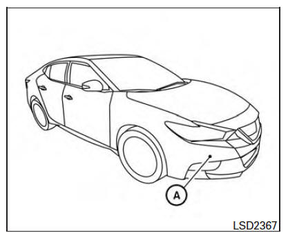
The ICC system is intended to enhance the operation of the vehicle when following a vehicle traveling in the same lane and direction.
The ICC system uses a radar sensor A located on the front of the vehicle to detect vehicles traveling ahead.
If the radar sensor detects a slower moving vehicle ahead, the system will reduce the vehicle speed so that your vehicle follows the vehicle in front at the selected distance.
The detection range of the sensor is approximately 390 ft (120 m) ahead.
- ICC system operation
- The ICC switch
- ICC system limitations
- System temporarily unavailable
- System maintenance
 Cruise control operations
The cruise control allows driving at a speed between
25 - 89 mph (40 - 144 km/h) without
keeping your foot on the accelerator pedal.
To turn on the cruise control, push the
switch on. The CRUI ...
 ICC system operation
The ICC system maintains a selected distance
from the vehicle in front of you within the speed
range 0 to 90 mph (0 to 144km/h) up to the set
speed. The set speed can be selected by the
driver ...
Other materials:
Center speaker
Description
The AV control unit sends audio signals to the BOSE speaker amp. The BOSE
speaker amp. amplifies the
audio signals before sending them to the center speaker using the audio signal
circuits.
Diagnosis Procedure
1.CONNECTOR CHECK
Check the AV control unit, BOSE speaker amp. and s ...
Uniform tire quality grading
DOT (Department of Transportation) Quality
Grades: All passenger car tires must conform to
federal safety requirements in addition to these
grades.
Quality grades can be found where applicable on
the tire sidewall between tread shoulder and
maximum section width. For example:
Treadwear 200 ...
Precaution
Precaution for Supplemental Restraint System (SRS) "AIR BAG" and
"SEAT BELT PRE-TENSIONER"
The Supplemental Restraint System such as "AIR BAG" and "SEAT BELT
PRE-TENSIONER", used along with a front seat belt, helps to reduce the risk
or severity of injury to the driver and front passenger for ...
Nissan Maxima Owners Manual
- Illustrated table of contents
- Safety-Seats, seat belts and supplemental restraint system
- Instruments and controls
- Pre-driving checks and adjustments
- Monitor, climate, audio, phone and voice recognition systems
- Starting and driving
- In case of emergency
- Appearance and care
- Do-it-yourself
- Maintenance and schedules
- Technical and consumer information
Nissan Maxima Service and Repair Manual

0.0079