Nissan Maxima Service and Repair Manual: Front wiper motor lo circuit
Component Function Check
1. CHECK FRONT WIPER LO OPERATION
IPDM E/R AUTO ACTIVE TEST
- Start IPDM E/R auto active test. Refer to PCS-11, "Diagnosis Description".
- Check that the front wiper operates at the LO operation.
CONSULT ACTIVE TEST
- Select "FRONT WIPER" of IPDM E/R active test item.
- While operating the test item, check front wiper LO operation and OFF.
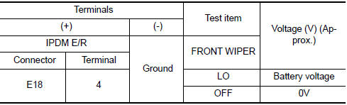
LO : Front wiper LO operation<>
OFF : Stop the front wiper.
Diagnosis Procedure
1. CHECK FRONT WIPER MOTOR (LO) OUTPUT VOLTAGE
CONSULT ACTIVE TEST
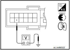
- Turn the ignition switch OFF.
- Disconnect front wiper motor.
- Turn the ignition switch ON.
- Select "FRONT WIPER" of IPDM E/R active test item.
- While operating the test item, check voltage between IPDM E/R
harness connector and ground.
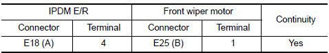
2. CHECK FRONT WIPER MOTOR (LO) OPEN CIRCUIT
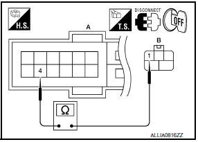
- Turn the ignition switch OFF.
- Disconnect IPDM E/R.
- Check continuity between IPDM E/R harness connector (A) and
front wiper motor harness connector (B).
 Wiper and washer fuse
Description
Fuse list
Diagnosis Procedure
1. CHECK FUSES
Check that the following fuses are not blown.
...
 Front wiper motor hi circuit
Component Function Check
1. CHECK FRONT WIPER HI OPERATION
IPDM E/R AUTO ACTIVE TEST
Start IPDM E/R auto active test. Refer to PCS-11, "Diagnosis
Description".
Check that the front wiper op ...
Other materials:
Driver Attention Alert system operation
If the system detects driver fatigue or that driver
attention is decreasing, the message "Take a
break?"appears in the vehicle information display
and a chime sounds when the vehicle is driven at
speeds above 37 mph (60 km/h).
The system continuously monitors driver attention
and can pro ...
Microphone signal circuit
Description
Voice signals are transmitted from the microphone to the AV control unit
using the microphone signal circuits.
Diagnosis Procedure
1.CHECK HARNESS BETWEEN AV CONTROL UNIT AND MICROPHONE
Turn ignition switch OFF.
Disconnect AV control unit connector and microphone connector ...
How to read the displayed lines
Guiding lines which indicate the vehicle width
and distances to objects with reference to the
vehicle body line A are displayed on the monitor.
Distance guide lines
Indicate distances from the vehicle body.
Red line 1 : approx. 1.5 ft (0.5 m)
Yellow line 2 : approx. 3 ft (1 m)
Green ...
Nissan Maxima Owners Manual
- Illustrated table of contents
- Safety-Seats, seat belts and supplemental restraint system
- Instruments and controls
- Pre-driving checks and adjustments
- Monitor, climate, audio, phone and voice recognition systems
- Starting and driving
- In case of emergency
- Appearance and care
- Do-it-yourself
- Maintenance and schedules
- Technical and consumer information
Nissan Maxima Service and Repair Manual

0.0066