Nissan Maxima Service and Repair Manual: B210F transmission range switch
Description
IPDM E/R confirms the shift position with the following signals.
-
Transmission range switch
-
Shift position signal from BCM (CAN)
DTC Logic
DTC DETECTION LOGIC
NOTE:
-
If DTC B210F is displayed with DTC U1000, first perform the trouble diagnosis for DTC U1000. Refer to SEC-29, "DTC Logic"
-
If DTC B210F is displayed with DTC U1010, first perform the trouble diagnosis for DTC U1010. Refer to SEC-30, "DTC Logic".

DTC CONFIRMATION PROCEDURE
1.PERFORM DTC CONFIRMATION PROCEDURE
-
Turn ignition switch ON under the following conditions and wait for at least 1 second.
-
CVT selector lever is in the P or N position
-
Do not depress the brake pedal
-
-
Check "Self diagnostic result" with CONSULT.
Diagnosis Procedure
Regarding Wiring Diagram information, refer to SEC-147, "Wiring Diagram" or SEC-128, "Wiring Diagram".
1.CHECK DTC WITH BCM
Refer to BCS-64, "DTC Index".
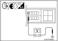
2.CHECK TRANSMISSION RANGE SWITCH INPUT SIGNAL
-
Turn ignition switch OFF.
-
Disconnect IPDM E/R harness connector.
-
Turn ignition switch ON.
-
Check voltage between IPDM E/R harness connector E18 terminal 30 and ground under following condition.


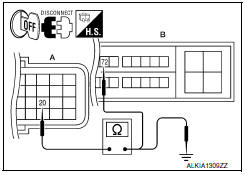
3.CHECK TRANSMISSION RANGE SWITCH CIRCUIT
-
Turn ignition switch OFF.
-
Disconnect TCM harness connector.
-
Check continuity between IPDM E/R harness connector E18 (B) terminal 72 and TCM harness connector F15 (A) terminal 20.


4. Check continuity between TCM harness connector F15 (A) terminal 20 and ground.

4.CHECK INTERMITTENT INCIDENT
Refer to GI-41, "Intermittent Incident".
Inspection End.
 B210E starter relay
DTC Logic
DTC DETECTION LOGIC
NOTE:
If DTC B210E is displayed with DTC
U1000, first perform the trouble diagnosis for DTC U1000. Refer to
SEC-29, "DTC Logic".
If DTC B210E is di ...
 B2110 transmission range switch
Description
IPDM E/R confirms the shift position with the following
signals.
Transmission range switch
Shift position signal from BCM (CAN)
DTC Logic
DTC DETECTION ...
Other materials:
Front door switch (driver side)
Description
Detects front door LH open/close condition.
Component Function Check
1. CHECK FUNCTION
Select "DOOR SW-FL" in "DATA MONITOR" mode with CONSULT.
Check the front door switch signal under the following conditions
Diagnosis Procedure
1. CHECK FRONT DOOR SWITCH LH CIRCUIT
...
Optical sensor
Exploded View
Optical sensor
LH front tweeter speaker grille
Optical sensor harness connector
LH front tweeter speaker
Instrument panel
Removal and Installation
CAUTION: Whenever a suitable tool is used,
always wrap a cloth around the end of the tool to protect components from ...
Diagnosis and repair workflow
Work Flow
OVERALL SEQUENCE
DETAILED FLOW
1. GET INFORMATION FOR SYMPTOM
Get the detailed information from the customer about the symptom (the
condition and the environment when
the incident/malfunction occurred).
2. CHECK DTC
Check DTC.
Perform the following procedure if DTC is ...
Nissan Maxima Owners Manual
- Illustrated table of contents
- Safety-Seats, seat belts and supplemental restraint system
- Instruments and controls
- Pre-driving checks and adjustments
- Monitor, climate, audio, phone and voice recognition systems
- Starting and driving
- In case of emergency
- Appearance and care
- Do-it-yourself
- Maintenance and schedules
- Technical and consumer information
Nissan Maxima Service and Repair Manual
0.0275
