Nissan Maxima Service and Repair Manual: B2110 transmission range switch
Description
IPDM E/R confirms the shift position with the following signals.
-
Transmission range switch
-
Shift position signal from BCM (CAN)
DTC Logic
DTC DETECTION LOGIC
NOTE:
-
If DTC B2110 is displayed with DTC U1000, first perform the trouble diagnosis for DTC U1000. Refer to SEC-29, "DTC Logic".
-
If DTC B2110 is displayed with DTC U1010, first perform the trouble diagnosis for DTC U1010. Refer to SEC-30, "DTC Logic".

DTC CONFIRMATION PROCEDURE
1.PERFORM DTC CONFIRMATION PROCEDURE
-
Turn the ignition switch ON under the following conditions and wait for at least 1 second.
-
CVT selector lever is in the P or N position
-
Do not depress the brake pedal
-
-
Check "Self diagnostic result" with CONSULT.
Diagnosis Procedure
Regarding Wiring Diagram information, refer to SEC-147, "Wiring Diagram" or SEC-128, "Wiring Diagram".
1.CHECK DTC WITH BCM
Refer to BCS-64, "DTC Index".
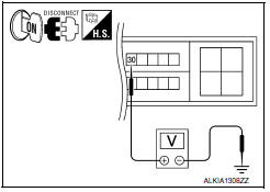
2.CHECK TRANSMISSION RANGE SWITCH INPUT SIGNAL
-
Turn ignition switch OFF.
-
Disconnect IPDM E/R harness connector.
-
Turn ignition switch ON.
-
Check voltage between IPDM E/R harness connector E18 terminal 30 and ground under following condition.


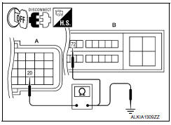
3.CHECK TRANSMISSION RANGE SWITCH CIRCUIT
-
Turn ignition switch OFF.
-
Disconnect TCM harness connector.
-
Check continuity between IPDM E/R harness connector E18 (B) terminal 72 and TCM harness connector F15 (A) terminal 20.


4. Check continuity between TCM harness connector F15 (A) terminal 20 and ground.

4.CHECK INTERMITTENT INCIDENT
Refer to GI-41, "Intermittent Incident".
Inspection End.
 B210F transmission range switch
Description
IPDM E/R confirms the shift position with the following
signals.
Transmission range switch
Shift position signal from BCM (CAN)
DTC Logic
DTC DETECTION ...
 Power supply and ground circuit
BCM
BCM : Diagnosis Procedure
Regarding Wiring Diagram information, refer to BCS-67,
"Wiring Diagram".
1. CHECK FUSE AND FUSIBLE LINK
Check if the following BCM fuses or fusible link are
blown ...
Other materials:
License plate lamp
Exploded View
License plate lamp
Removal and Installation
LICENSE PLATE LAMP
Removal'
Remove the license lamp finisher. Refer to EXT-31, "Removal and
Installation".
Position trunk lid finisher aside. Refer to INT-36, "Exploded
View".
Remove the license plate lamp screw and ...
Air conditioner system refrigerant and oil recommendations
The air conditioner system in your NISSAN
vehicle must be charged with the refrigerant
HFC-134a (R-134a) and Genuine
NISSAN A/C System Oil Type ND-OIL8 or
the exact equivalents.
CAUTION
The use of any other refrigerant or oil may
cause severe damage to the air conditioning
system and may req ...
ABS
System Diagram
System Description
Anti-Lock Braking System is a function that detects wheel revolution
while braking, electronically controls
braking force, and prevents wheel locking during sudden braking. It improves
handling stability and maneuverability
for avoiding obstacle ...
Nissan Maxima Owners Manual
- Illustrated table of contents
- Safety-Seats, seat belts and supplemental restraint system
- Instruments and controls
- Pre-driving checks and adjustments
- Monitor, climate, audio, phone and voice recognition systems
- Starting and driving
- In case of emergency
- Appearance and care
- Do-it-yourself
- Maintenance and schedules
- Technical and consumer information
Nissan Maxima Service and Repair Manual
0.0065
