Nissan Maxima Service and Repair Manual: Compass
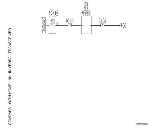
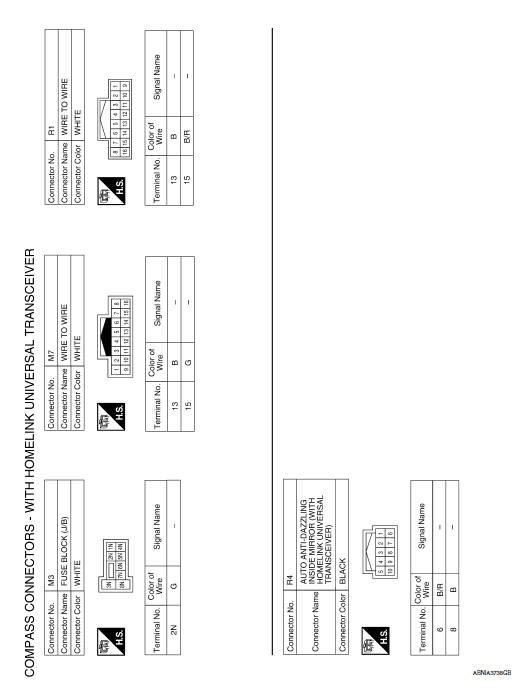
Wiring Diagram - WITH HOMELINK UNIVERSAL TRANSCEIVER
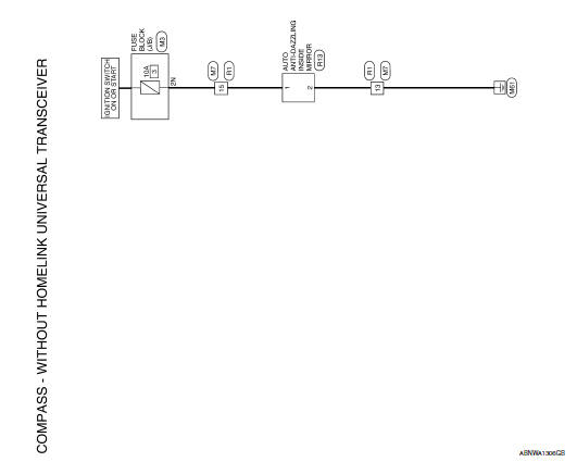
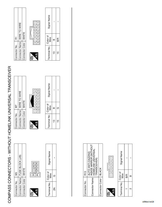
Wiring Diagram - WITHOUT HOMELINK UNIVERSAL TRANSCEIVER
 Meter
Meter
Wiring Diagram
...

Other materials:
Periodic maintenance
REAR SUSPENSION ASSEMBLY
On-vehicle Service
Check the suspension parts for excessive play, cracks, wear or damage.
Shake each rear wheel to check for excessive play.
Retighten all nuts and bolts to the specified torque.
Make sure that the cotter pin is installed.
Check the rear sho ...
M&A branch line circuit
Diagnosis Procedure
1.CHECK CONNECTOR
Turn the ignition switch OFF.
Disconnect the battery cable from the negative terminal.
Check the terminals and connectors of the combination meter for
damage, bend and loose connection
(unit side and connector side).
2.CHECK HARNESS FOR OPEN CI ...
Squeak and rattle trouble diagnoses
Work Flow
CUSTOMER INTERVIEW
Interview the customer if possible, to determine the conditions that exist
when the noise occurs. Use the Diagnostic Worksheet during the interview to
document the facts and conditions when the noise occurs and any customer's
comments; refer to RF-64, "Diagnost ...
Nissan Maxima Owners Manual
- Illustrated table of contents
- Safety-Seats, seat belts and supplemental restraint system
- Instruments and controls
- Pre-driving checks and adjustments
- Monitor, climate, audio, phone and voice recognition systems
- Starting and driving
- In case of emergency
- Appearance and care
- Do-it-yourself
- Maintenance and schedules
- Technical and consumer information
Nissan Maxima Service and Repair Manual

0.0065