Nissan Maxima Service and Repair Manual: Meter
Wiring Diagram
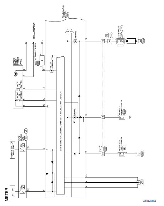
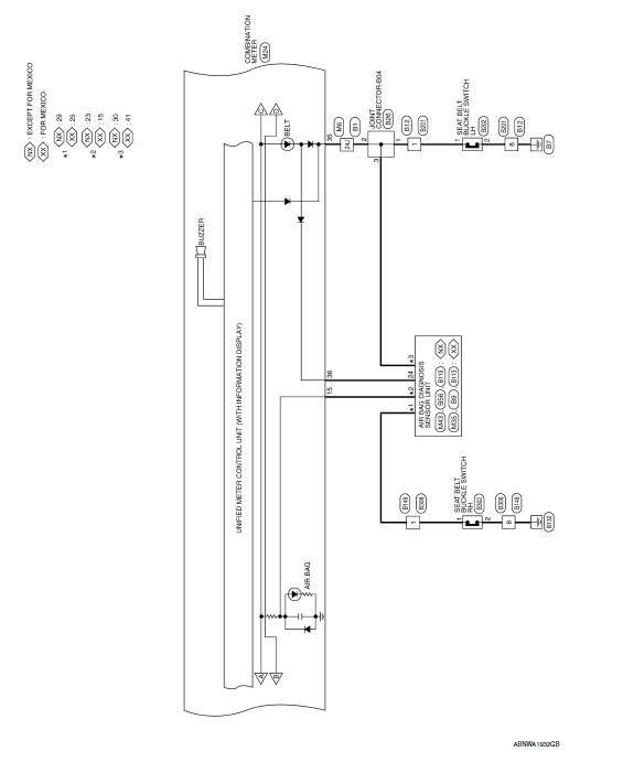
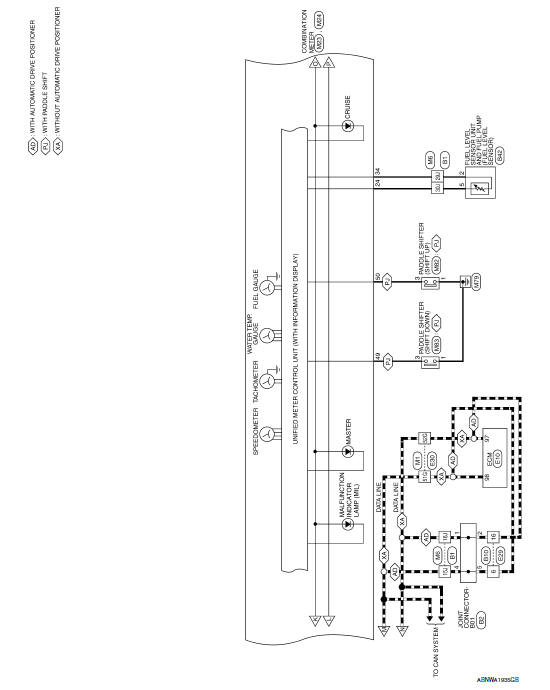
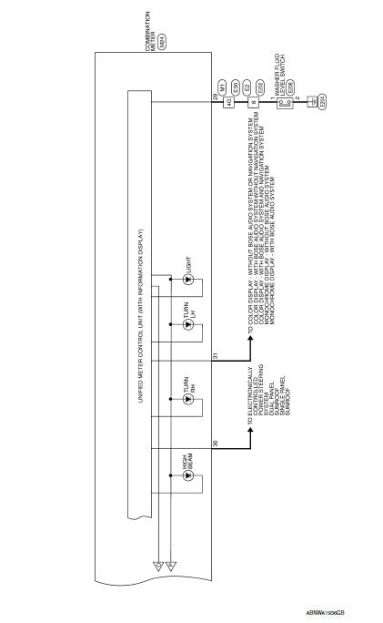
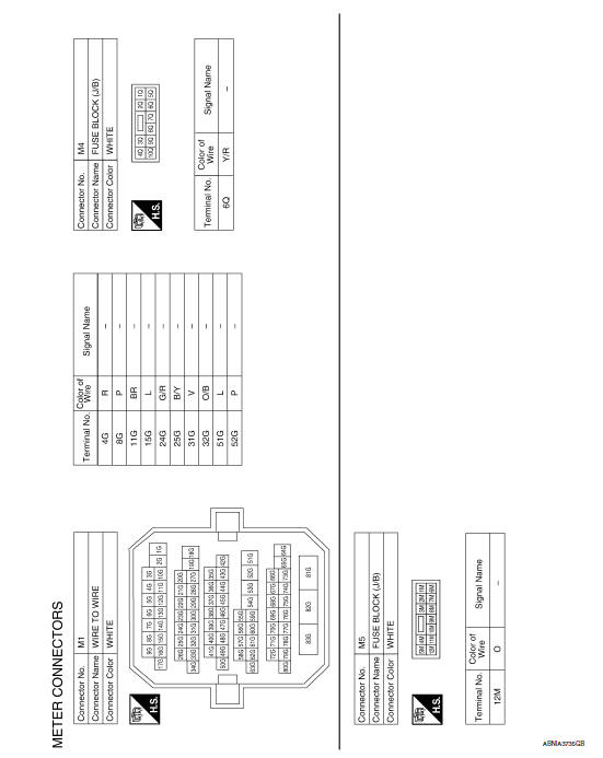
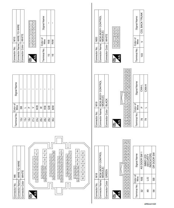
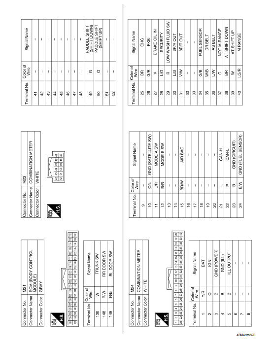
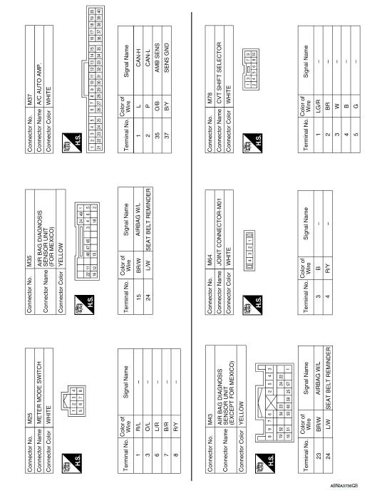
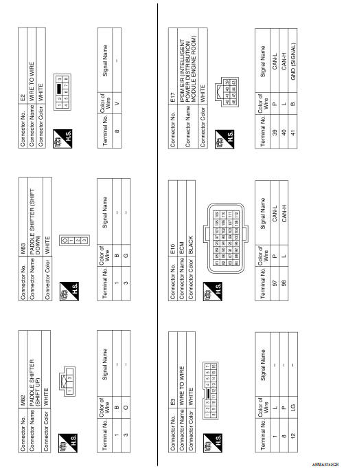
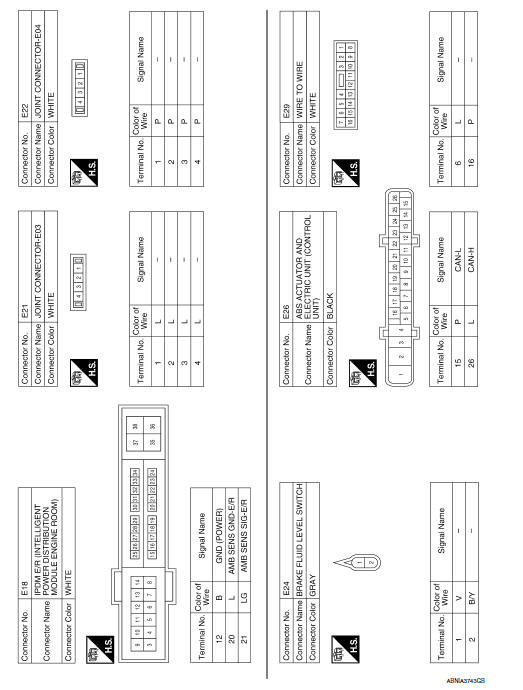
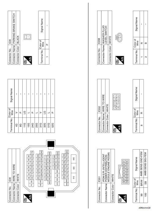
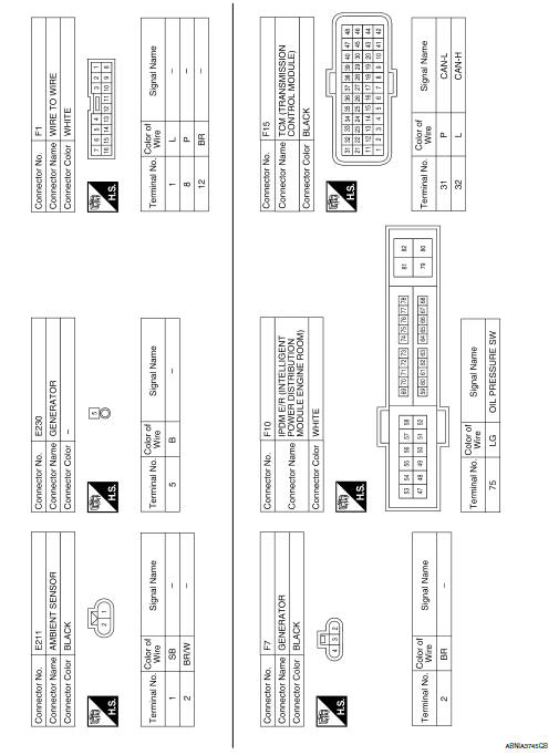
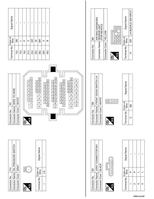
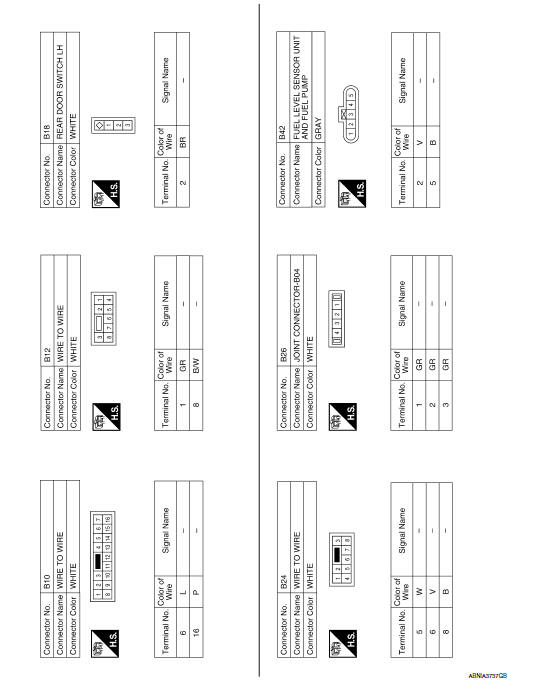
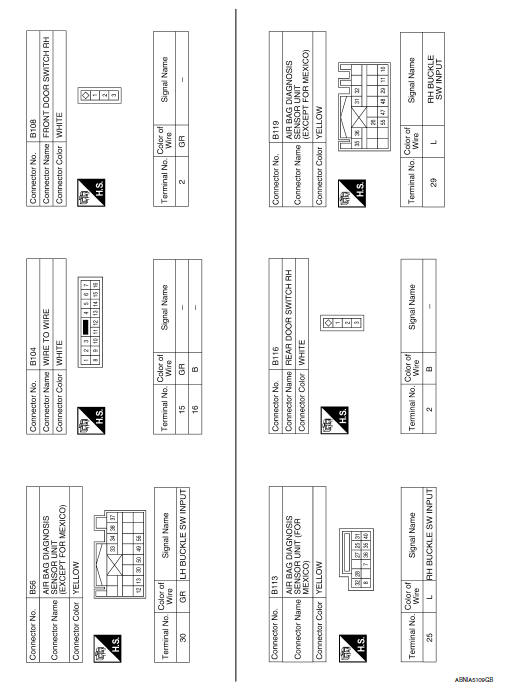
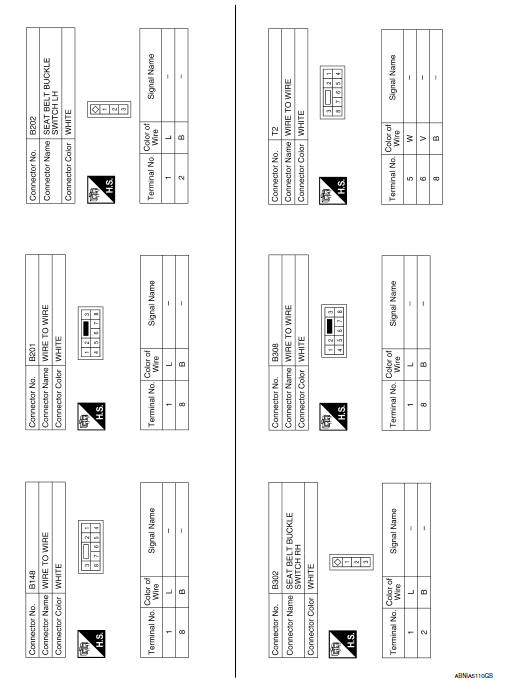
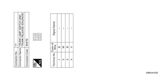
 Wiring diagram
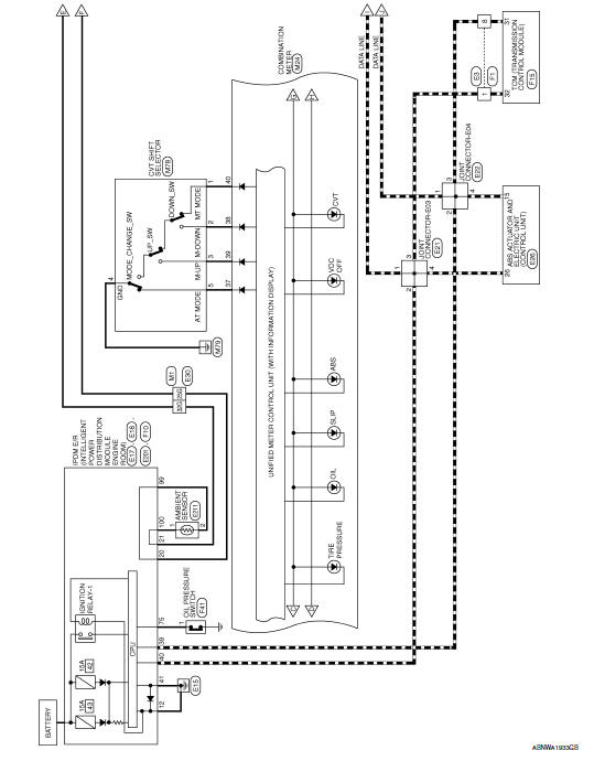
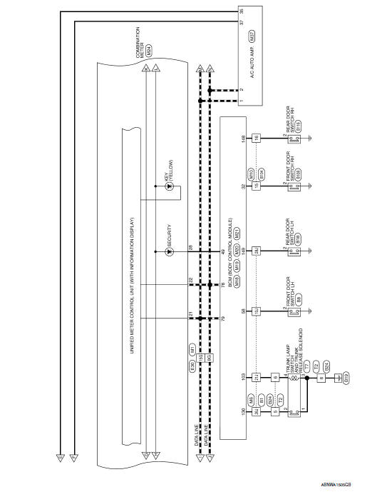
...
 Compass
Wiring Diagram - WITH HOMELINK UNIVERSAL TRANSCEIVER
Wiring Diagram - WITHOUT HOMELINK UNIVERSAL TRANSCEIVER
...
Other materials:
U1207 AV control unit
DTC Logic
Diagnosis Procedure
1.PERFORM THE SELF-DIAGNOSIS
Delete the "self-diagnosis" results of "MULTI AV". Turn ignition
switch OFF.
Turn ignition switch ON. Perform the self-diagnosis again.
Check that the DTC is detected again.
U1216 AV CONTROL UNIT
DTC Logic
U1217 AV ...
Power supply and ground circuit
BCM
BCM : Diagnosis Procedure
1. CHECK FUSE AND FUSIBLE LINK
Check if the following BCM fuses or fusible link are blown.
2. CHECK POWER SUPPLY CIRCUIT
Turn ignition switch OFF.
Disconnect BCM.
Check voltage between BCM harness connector and ground.
3. CHECK GROUND CIRCUIT
Che ...
Front door speaker
Removal and Installation
REMOVAL
Remove the front door finisher. Refer to INT-18, "Removal and
Installation".
Remove the front door speaker screws (A).
Disconnect the harness connector from the front door speaker
(1) and remove.
Remove the front door speaker spacer screws (B) and ...
Nissan Maxima Owners Manual
- Illustrated table of contents
- Safety-Seats, seat belts and supplemental restraint system
- Instruments and controls
- Pre-driving checks and adjustments
- Monitor, climate, audio, phone and voice recognition systems
- Starting and driving
- In case of emergency
- Appearance and care
- Do-it-yourself
- Maintenance and schedules
- Technical and consumer information
Nissan Maxima Service and Repair Manual

0.0054