Nissan Maxima Service and Repair Manual: U1001 can comm circuit
Description
CAN (Controller Area Network) is a serial communication line for real time application. It is an on-vehicle multiplex communication line with high data communication speed and excellent error detection ability. Many electronic control units are equipped onto a vehicle, and each control unit shares information and links with other control units during operation (not independent). In CAN communication, control units are connected with 2 communication lines (CAN H line, CAN L line) allowing a high rate of information transmission with less wiring.
Each control unit transmits/receives data but selectively reads required data only.
DTC Logic
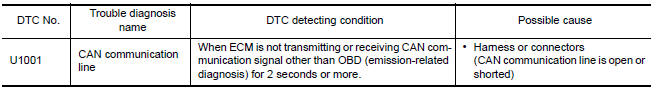
DTC DETECTION LOGIC
DTC CONFIRMATION PROCEDURE
1.PERFORM DTC CONFIRMATION PROCEDURE
- Turn ignition switch ON and wait at least 3 seconds.
- Check DTC.
Diagnosis Procedure
 U0101 can comm circuit
Description
CAN (Controller Area Network) is a serial communication line for real time
application. It is an on-vehicle multiplex
communication line with high data communication speed and excelle ...
 P0011, P0021 IVT control
DTC Logic
DTC DETECTION LOGIC
NOTE:
If DTC P0011 or P0021 is displayed with DTC P0075, P0081, first perform the
trouble diagnosis for DTC
P0075, P0081.
DTC CONFIRMATION PROCEDURE
1.PRECO ...
Other materials:
The low washer fluid warning continues displaying, or does not display
Description
The warning is still displayed even after
washer fluid is added.
The warning is not displayed even though the
washer tank is empty.
Diagnosis Procedure
1.CHECK WASHER FLUID LEVEL SWITCH SIGNAL CIRCUIT
Check the washer fluid level switch signal cir ...
Unit disassembly and assembly
FRONT COIL SPRING AND STRUT
Disassembly and Assembly
DISASSEMBLY
Install Tool (A) to the front coil spring and strut.
Tool number : ST35652000 ( - )
CAUTION: When installing Tool (A), wrap a
shop cloth around the front coil spring and strut to protect the parts from
damage.
Sec ...
Sunglasses holder
To open the sunglasses holder, push and release.
Only store one pair of sunglasses in the holder.
WARNING
Keep the sunglasses holder closed while
driving to avoid obstructing the driver's
view and to help prevent an accident.
CAUTION
Do not use for anything other than
sunglasses.
...
Nissan Maxima Owners Manual
- Illustrated table of contents
- Safety-Seats, seat belts and supplemental restraint system
- Instruments and controls
- Pre-driving checks and adjustments
- Monitor, climate, audio, phone and voice recognition systems
- Starting and driving
- In case of emergency
- Appearance and care
- Do-it-yourself
- Maintenance and schedules
- Technical and consumer information
Nissan Maxima Service and Repair Manual

0.008