Nissan Maxima Service and Repair Manual: Display unit
Reference Value
TERMINAL LAYOUT
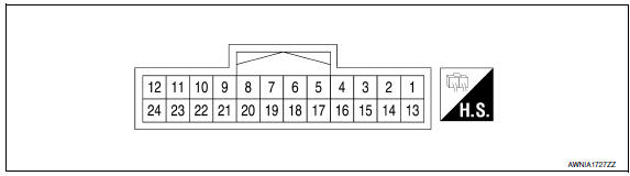
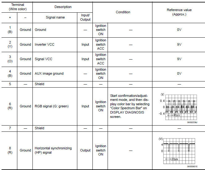
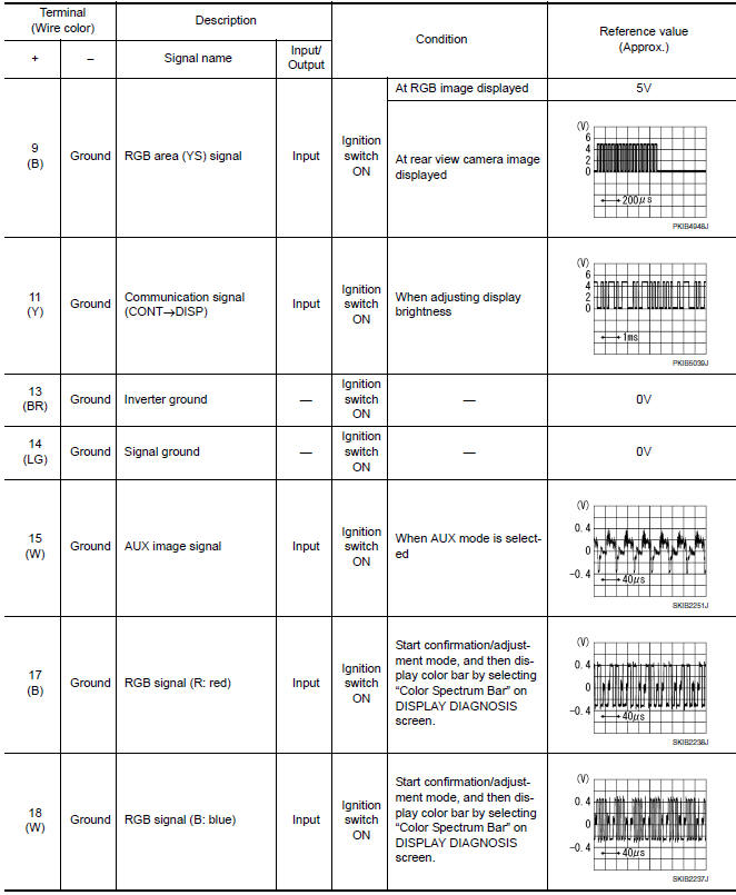
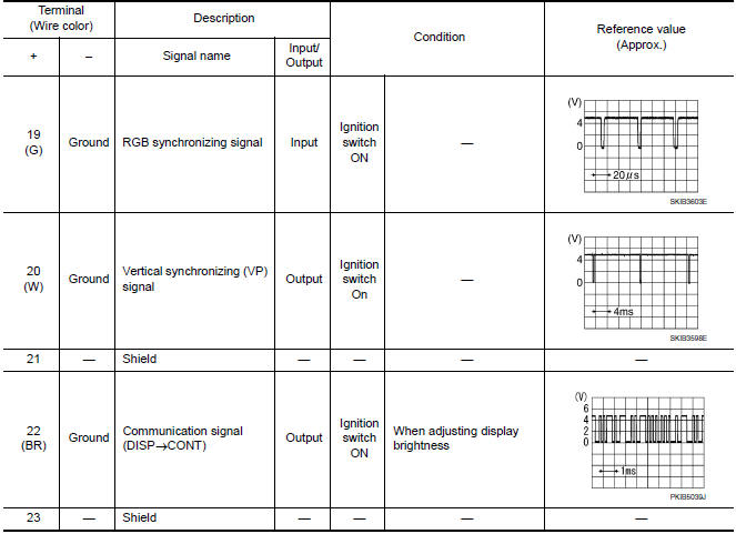
PHYSICAL VALUES
 AV control unit
Reference Value
VALUES ON THE DIAGNOSIS TOOL
CONSULT data monitor item
TERMINAL LAYOUT
PHYSICAL VALUES
*1 With satellite radio
DTC Index
Self-diagnosis results d ...
 Bose speaker amp
Reference Value
TERMINAL LAYOUT
PHYSICAL VALUES
...
Other materials:
P0112, P0113 IAT sensor
Description
The intake air temperature sensor is built-into the mass air flow sensor
(1). The sensor detects intake air temperature and transmits a
signal to the ECM.
The temperature sensing unit uses a thermistor which is sensitive to
the change in temperature. Electrical resistance of ...
Tire and loading information label
Seating capacity: The maximum number
of occupants that can be seated
in the vehicle.
Vehicle load limit: Refer to the loading
information in the "Technical and
consumer information" section of this
manual.
Original tire size: The size of the tires
originally installed on the v ...
Adjusting the screen
1. Touch the touch-screen display with the
Around View Monitor on.
2. Touch the "Brightness," "Contrast," "Tint,"
"Color," or "Black Level" key.
3. Adjust the item by touching the + or - key
on the touch-screen display.
NOTE:
Do not adjust any of the display settings of
the Around Vi ...
Nissan Maxima Owners Manual
- Illustrated table of contents
- Safety-Seats, seat belts and supplemental restraint system
- Instruments and controls
- Pre-driving checks and adjustments
- Monitor, climate, audio, phone and voice recognition systems
- Starting and driving
- In case of emergency
- Appearance and care
- Do-it-yourself
- Maintenance and schedules
- Technical and consumer information
Nissan Maxima Service and Repair Manual

0.0064