Nissan Maxima Service and Repair Manual: Basic inspection
DIAGNOSIS AND REPAIR WORKFLOW
Work Flow
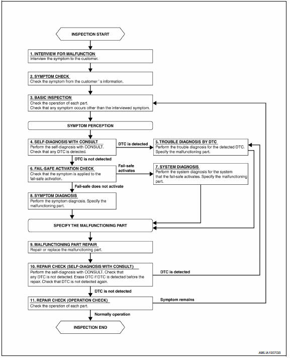
OVERALL SEQUENCE
DETAILED FLOW
1.INTERVIEW FOR MALFUNCTION
Find out what the customer's concerns are.
2.SYMPTOM CHECK
Verify the symptom from the customer's information.
3.BASIC INSPECTION
Check the operation of each part. Check that any concerns occur other than those mentioned in the customer interview.
4.SELF-DIAGNOSIS WITH CONSULT
Perform the self-diagnosis with CONSULT. Check that any DTC is detected.
5.TROUBLE DIAGNOSIS BY DTC
Perform the trouble diagnosis for the detected DTC. Specify the malfunctioning part.
6.FAIL-SAFE ACTIVATION CHECK
Determine if the customer's concern is related to fail-safe activation.
7.SYSTEM DIAGNOSIS
Perform the system diagnosis for the system in which the fail-safe activates. Specify the malfunctioning part.
8.SYMPTOM DIAGNOSIS
Perform the symptom diagnosis. Refer to INL-81, "Symptom Table". Specify the malfunctioning part.
9.MALFUNCTION PART REPAIR
Repair or replace the malfunctioning part.
10.REPAIR CHECK (SELF-DIAGNOSIS WITH CONSULT)
Perform the self-diagnosis with CONSULT. Verify that no DTCs are detected. Erase all DTCs detected prior to the repair. Verify that DTC is not detected again.
11.REPAIR CHECK (OPERATION CHECK)
Check the operation of each part.


Other materials:
Lifting motor (rear)
Description
The lifting motor (rear) is installed to the seat frame.
The lifting motor (rear) is activated with the driver seat control
unit.
The seat lifter (rear) is moved upward/downward by changing the
rotation direction of lifting motor (rear).
Component Function Check
1. CHEC ...
U1243 display unit
DTC Logic
Diagnosis Procedure
1.CHECK DISPLAY UNIT POWER SUPPLY AND GROUND CIRCUIT
Check display unit power supply and ground circuit
2.CHECK CONTINUITY OF COMMUNICATION CIRCUIT
Turn ignition switch OFF.
Disconnect display unit connector M142 and AV control unit
connector M163.
...
Under the hood and vehicle
The maintenance items listed here should be
checked periodically (for example, each time you
check the engine oil or refuel).
Battery*: Check the fluid level in each cell. The
fluid should be at the bottom of the filler opening.
Vehicles operated in high temperatures or under
severe condit ...
Nissan Maxima Owners Manual
- Illustrated table of contents
- Safety-Seats, seat belts and supplemental restraint system
- Instruments and controls
- Pre-driving checks and adjustments
- Monitor, climate, audio, phone and voice recognition systems
- Starting and driving
- In case of emergency
- Appearance and care
- Do-it-yourself
- Maintenance and schedules
- Technical and consumer information
Nissan Maxima Service and Repair Manual

0.006