Nissan Maxima Service and Repair Manual: Power supply and ground circuit
BCM
BCM : Diagnosis Procedure
Regarding Wiring Diagram information, refer to BCS-67, "Wiring Diagram".
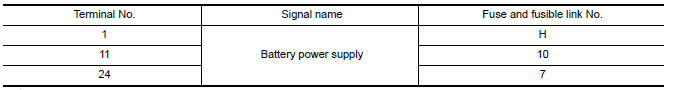
1. CHECK FUSE AND FUSIBLE LINK
Check if the following BCM fuses or fusible link are blown.
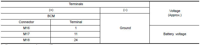
2. CHECK POWER SUPPLY CIRCUIT
-
Turn ignition switch OFF.
-
Disconnect BCM.
-
Check voltage between BCM harness connector and ground.
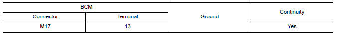
3. CHECK GROUND CIRCUIT
Check continuity between BCM harness connector and ground.
BCM : Special Repair Requirement
1. REQUIRED WORK WHEN REPLACING BCM
Initialize control unit. Refer to BCS-5, "ADDITIONAL SERVICE WHEN REPLACING CONTROL UNIT (BCM) :
Work Procedure".
Work End.
 B2110 transmission range switch
Description
IPDM E/R confirms the shift position with the following
signals.
Transmission range switch
Shift position signal from BCM (CAN)
DTC Logic
DTC DETECTION ...
 IPDM E/R (intelligent power distribution module engine room)
IPDM E/R (INTELLIGENT POWER DISTRIBUTION MODULE ENGINE
ROOM) : Diagnosis
Procedure
Regarding Wiring Diagram information, refer to PCS-28,
"Wiring Diagram".
1. CHECK FUSES AND FUSIBLE LINK
Che ...
Other materials:
Unexpected pedal reaction
Diagnosis Procedure
1.CHECK BRAKE PEDAL STROKE
Check brake pedal stroke.
2.CHECK FUNCTION
Disconnect ABS actuator and electric unit (control unit) connector to
deactivate ABS. Check if braking force is
normal in this condition.Connect connector after inspection.
3.CHECK WHEEL SENSOR AND SEN ...
Precaution
PRECAUTIONS
Precaution for Supplemental Restraint System (SRS) "AIR BAG" and "SEAT BELT
PRE-TENSIONER"
The Supplemental Restraint System such as "AIR BAG" and "SEAT BELT
PRE-TENSIONER", used along
with a front seat belt, helps to reduce the risk or severity of injury to the
driver and fron ...
B1081 - B1084 seat belt pre-tensioner RH
Description
DTC B1081 - B1084 SEAT BELT PRE-TENSIONER RH
The seat belt pre-tensioner RH is wired to the air bag diagnosis sensor unit.
The air bag diagnosis sensor unitwill monitor for opens and shorts in
detected lines to the seat belt pre-tensioner RH.
PART LOCATION
DTC Logic
DTC DETECTIO ...
Nissan Maxima Owners Manual
- Illustrated table of contents
- Safety-Seats, seat belts and supplemental restraint system
- Instruments and controls
- Pre-driving checks and adjustments
- Monitor, climate, audio, phone and voice recognition systems
- Starting and driving
- In case of emergency
- Appearance and care
- Do-it-yourself
- Maintenance and schedules
- Technical and consumer information
Nissan Maxima Service and Repair Manual

0.0071