Nissan Maxima Service and Repair Manual: IPDM E/R (intelligent power distribution module engine room)
IPDM E/R (INTELLIGENT POWER DISTRIBUTION MODULE ENGINE ROOM) : Diagnosis Procedure
Regarding Wiring Diagram information, refer to PCS-28, "Wiring Diagram".
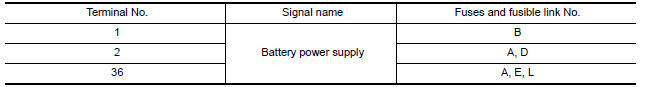
1. CHECK FUSES AND FUSIBLE LINK
Check that the following IPDM E/R fuses or fusible link are not blown.
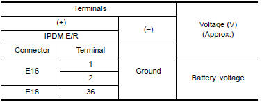
2. CHECK POWER SUPPLY CIRCUIT
-
Turn ignition switch OFF.
-
Disconnect IPDM E/R connectors.
-
Check voltage between IPDM E/R harness connector and ground.
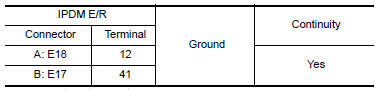
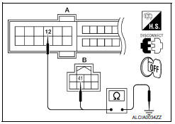
3. CHECK GROUND CIRCUIT
Check continuity between IPDM E/R harness connectors and ground.
 Power supply and ground circuit
BCM
BCM : Diagnosis Procedure
Regarding Wiring Diagram information, refer to BCS-67,
"Wiring Diagram".
1. CHECK FUSE AND FUSIBLE LINK
Check if the following BCM fuses or fusible link are
blown ...
 Key slot
Diagnosis Procedure
Regarding Wiring Diagram information, refer to SEC-147,
"Wiring Diagram" or SEC-128, "Wiring Diagram".
1.CHECK KEY SLOT POWER SUPPLY CIRCUIT
Turn ignition switch O ...
Other materials:
Starting the engine
1. Apply the parking brake.
2. Move the shift lever to P (Park) or N (Neutral).
P (Park) is recommended.
The starter is designed not to operate if
the shift lever is in any of the driving
positions.
3. Push the ignition switch to the ON position.
Depress the brake pedal and push the ign ...
Parking, license plate and tail lamps
System Diagram
System Description
BCM (Body Control Module) controls parking, license plate and tail lamps
operation.
IPDM E/R (Intelligent Power Distribution Module Engine Room) operates
parking, license plate and tail lamps according to CAN communication
signals from BCM.
Comp ...
Hazard function
Symptom Table
HAZARD AND BUZZER REMINDER FUNCTION MALFUNCTION
NOTE:
Before performing the diagnosis in the following table, check
"Work flow". Refer to DLK-9, "Work Flow".
If the following symptoms are detected, check systems shown in
the "Diagnosis/service procedure" column ...
Nissan Maxima Owners Manual
- Illustrated table of contents
- Safety-Seats, seat belts and supplemental restraint system
- Instruments and controls
- Pre-driving checks and adjustments
- Monitor, climate, audio, phone and voice recognition systems
- Starting and driving
- In case of emergency
- Appearance and care
- Do-it-yourself
- Maintenance and schedules
- Technical and consumer information
Nissan Maxima Service and Repair Manual

0.0062