Nissan Maxima Service and Repair Manual: Climate controlled seat switch
Description
Provides inputs to the climate controlled seat control unit for climate controlled seat operation.
Component Function Check
1.CHECK CLIMATE CONTROLLED SEAT SWITCH FUNCTION
Turn the climate controlled seat switch to the H (Heat) LO, MED, and HI positions and the C (Cool) LO, MED, and HI positions. Check that the climate controlled seat operates at low, medium and high heat, and low, medium and high cool.
Diagnosis Procedure
Regarding Wiring Diagram information, refer to SE-44, "Wiring Diagram".
1.CHECK CLIMATE CONTROLLED SEAT SWITCH
Perform climate controlled seat switch component inspection. Refer to SE-21, "Component Inspection (Climate Controlled Seat Switch)".
2.CHECK CLIMATE CONTROLLED SEAT SWITCH POWER SUPPLY CIRCUIT
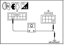
- Turn ignition switch OFF.
- Disconnect climate controlled seat switch connector and climate controlled seat control unit connector B216.
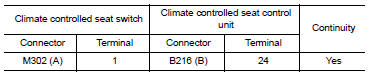
- Check continuity between climate controlled seat switch connector M302 (A) terminal 1 and climate controlled seat control unit connector B216 (B) terminal 24.
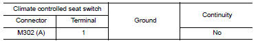
4. Check continuity between climate controlled seat switch connector M302 (A) terminal 1 and ground.
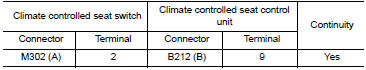
3.CHECK CLIMATE CONTROLLED SEAT SWITCH COOL CIRCUIT
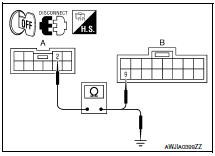
- Disconnect climate controlled seat control unit connector B212.
- Check continuity between climate controlled seat switch connector M302 (A) terminal 2 and climate controlled seat control unit connector B212 (B) terminal 9.
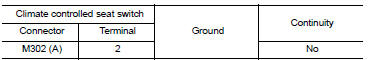
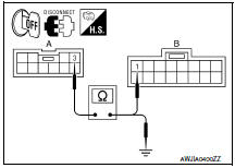
3. Check continuity between climate controlled seat switch connector M302 (A) terminal 2 and ground.
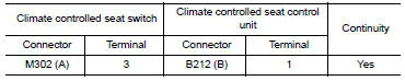
4.CHECK CLIMATE CONTROLLED SEAT SWITCH HEAT CIRCUIT
1. Check continuity between climate controlled seat switch connector M302 (A) terminal 3 and climate controlled seat control unit connector B212 (B) terminal 1.
2. Check continuity between climate controlled seat switch connector M302 (A) terminal 3 and ground.
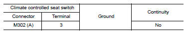
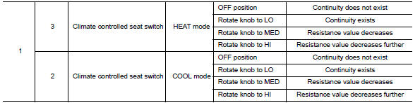
Component Inspection (Climate Controlled Seat Switch)
1.CHECK CLIMATE CONTROLLED SEAT SWITCH
- Disconnect climate controlled seat switch connector.
- Check continuity between climate controlled seat switch terminals.

 Seatback thermal electric device
Description
Provides cooling and heat for the seatback.
Component Function Check
1.CHECK SEATBACK THERMAL ELECTRIC DEVICE FUNCTION
Turn the climate controlled seat switch to the H (Heat) HI
...
 Climate controlled seat switch indicator
Description
Illuminates the climate controlled seat switch to indicate operating status.
Component Function Check
1.CHECK CLIMATE CONTROLLED SEAT SWITCH INDICATOR FUNCTION
Check that the indicator ...
Other materials:
Steering column
Disassembly and Assembly
The steering column assembly without electric motor is not serviceable and
must be replaced as an assembly.
With Electric Motor
Steering column assembly
Telescope motor
Telescope motor link bracket
Tilt motor
Tilt motor bolt cap
DISASSEMBLY
Remo ...
Antenna AMP
Removal and Installation
REMOVAL
Remove the rear pillar finisher RH. Refer to INT-23, "Exploded
View".
Detach the antenna amp. harness clip (A).
Disconnect the harness connectors (B) from the antenna amp.
(1).
Remove the antenna amp. screw (C) and the antenna amp. (1).
INSTALLAT ...
Service data and specifications (SDS)
SERVICE DATA AND SPECIFICATIONS (SDS)
Capacity
Thermostat
Radiator
...
Nissan Maxima Owners Manual
- Illustrated table of contents
- Safety-Seats, seat belts and supplemental restraint system
- Instruments and controls
- Pre-driving checks and adjustments
- Monitor, climate, audio, phone and voice recognition systems
- Starting and driving
- In case of emergency
- Appearance and care
- Do-it-yourself
- Maintenance and schedules
- Technical and consumer information
Nissan Maxima Service and Repair Manual

0.0056