Nissan Maxima Service and Repair Manual: U1000 CAN comm circuit
Description
CAN (Controller Area Network) is a serial communication line for real time application. It is an on-vehicle multiplex communication line with high data communication speed and excellent malfunction detection ability.
Many electronic control units are equipped onto a vehicle, and each control unit shares information and links with other control units during operation (not independent). In CAN communication, control units are connected with 2 communication lines (CAN-H and CAN-L) allowing a high rate of information transmission with less wiring. Each control unit transmits/receives data but selectively reads required data only.
DTC Logic
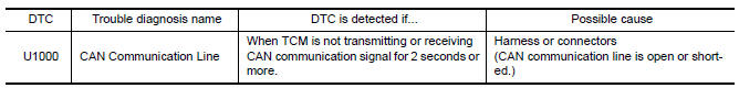
DTC DETECTION LOGIC
DTC CONFIRMATION PROCEDURE
NOTE: Immediately after performing any "DTC CONFIRMATION PROCEDURE", always turn ignition switch OFF.
Then wait at least 10 seconds before performing the next test.
1.CHECK DTC DETECTION
 With CONSULT
- Turn ignition switch ON.
- Start engine and wait for at least 6 seconds.
- Perform "Self Diagnostic Results" in "TRANSMISSION".
 With GST
Follow the procedure "With CONSULT".
Diagnosis Procedure
1.CHECK CAN COMMUNICATION CIRCUIT
 With CONSULT
- Turn ignition switch ON and start engine.
- Perform "Self Diagnostic Results" in "TRANSMISSION".
 U0100 lost communication (ECM A)
DTC Logic
DTC DETECTION LOGIC
DTC CONFIRMATION PROCEDURE
1.PREPARATION BEFORE WORK
If another "DTC CONFIRMATION PROCEDURE" occurs just before, turn ignition
switch OFF and wait for at
least ...
 U1010 control unit (CAN)
Description
CAN (Controller Area Network) is a serial communication line for real time
application. It is an on-vehicle multiplex
communication line with high data communication speed and excelle ...
Other materials:
A-bag branch line circuit
Diagnosis Procedure
WARNING:
Always observe the following items for preventing accidental
activation.
Before servicing, turn ignition switch OFF, disconnect battery negative
terminal, and wait 3 minutes or more. (To discharge backup capacitor.)
Never use unspecified tester or other measu ...
Power supply and ground circuit
Diagnosis Procedure
1.CHECK GROUND CONNECTION-I
Turn ignition switch OFF.
Check ground connection E9. Refer to Ground Inspection
2.CHECK ECM GROUND CIRCUIT FOR OPEN AND SHORT-I
Disconnect ECM harness connector.
Check the continuity between ECM harness connector and ground.
Also che ...
ECU diagnosis information
DIAGNOSIS SENSOR UNIT
Trouble Diagnosis with CONSULT
DIAGNOSTIC CODE CHART
NOTE:Follow the procedures in numerical
order when repairing malfunctioning parts. Confirm whether malfunction is
eliminated using air bag warning lamp or CONSULT each time repair is finished.
If malfunction is stillo ...
Nissan Maxima Owners Manual
- Illustrated table of contents
- Safety-Seats, seat belts and supplemental restraint system
- Instruments and controls
- Pre-driving checks and adjustments
- Monitor, climate, audio, phone and voice recognition systems
- Starting and driving
- In case of emergency
- Appearance and care
- Do-it-yourself
- Maintenance and schedules
- Technical and consumer information
Nissan Maxima Service and Repair Manual

0.0088