Nissan Maxima Service and Repair Manual: Electric ignition system
System Diagram
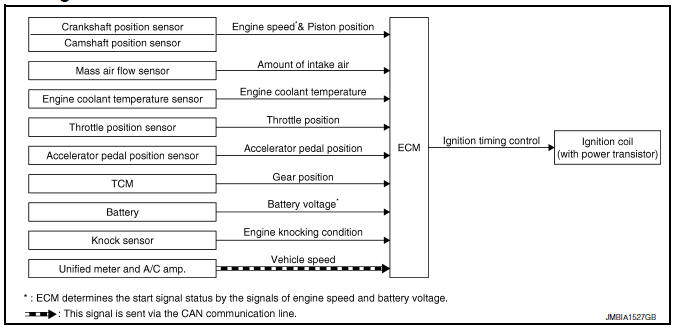
System Description
INPUT/OUTPUT SIGNAL CHART
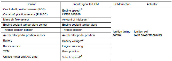
*1: This signal is sent to the ECM via the CAN communication line.
*2: ECM determines the start signal status by the signals of engine speed and
battery voltage.
SYSTEM DESCRIPTION
Ignition order: 1 - 2 - 3 - 4 - 5 - 6
The ignition timing is controlled by the ECM to maintain the best air-fuel ratio for every running condition of the engine. The ignition timing data is stored in the ECM.
The ECM receives information such as the injection pulse width and camshaft position sensor (PHASE) signal.
Computing this information, ignition signals are transmitted to the power transistor.
During the following conditions, the ignition timing is revised by the ECM according to the other data stored in the ECM.
- At starting
- During warm-up
- At idle
- At low battery voltage
- During acceleration
The knock sensor retard system is designed only for emergencies. The basic ignition timing is programmed within the anti-knocking zone, if recommended fuel is used under dry conditions. The retard system does not operate under normal driving conditions. If engine knocking occurs, the knock sensor monitors the condition.
The signal is transmitted to the ECM. The ECM retards the ignition timing to eliminate the knocking condition.
Component Parts Location
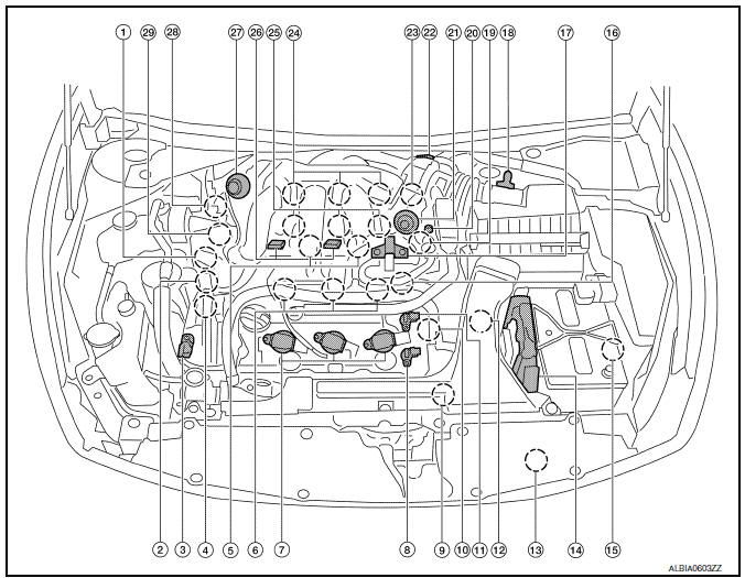
- Intake valve timing control solenoid valve (bank 1)
- Electronic controlled engine mount control solenoid valve
- Exhaust valve timing control magnet retarder (bank 2)
- Intake valve timing control solenoid valve (bank 2)
- Knock sensor (bank 1 and 2)
- Fuel injector (bank 2)
- Ignition coil (with power transistor) and spark plug (bank 2)
- Exhaust valve timing control position sensor (bank 2)
- Crankshaft position sensor (POS)
- Engine coolant temperature sensor
- Camshaft position sensor (PHASE) (bank 2)
- Transmission range switch
- Refrigerant pressure sensor
- ECM
- Battery current sensor
- . Condenser-2
- EVAP canister purge volume control solenoid valve
- Mass air flow sensor (with intake air temperature sensor)
- Camshaft position sensor (PHASE) (bank 1)
- EVAP service port
- Power valve actuator 2
- Electric throttle control actuator
- Exhaust valve timing control position sensor (bank 1)
- Ignition coil (with power transistor) and spark plug (bank 1)
- Fuel injector (bank 1)
- VIAS control solenoid valve 1 and 2
- Power valve actuator 1
- Exhaust valve timing control magnet retarder (bank 1)
- Power steering pressure sensor
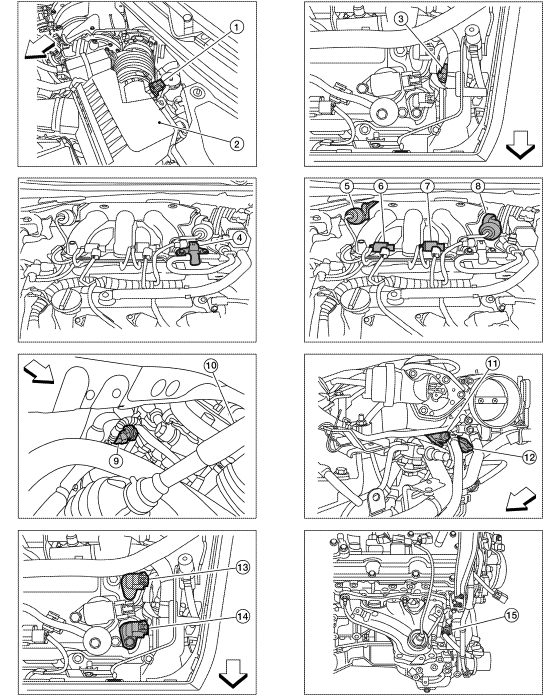
- Mas air flow sensor (with intake air temperature sensor)
- Air cleaner case
- Engine coolant temperature sensor (view with engine cover removed)
- EVAP canister purge volume control solenoid valve (view with engine cover removed)
- Power valve actuator 1 (view with engine cover removed)
- VIAS control solenoid valve 1
- VIAS control solenoid valve 2
- Power valve actuator 2
- Power steering pressure sensor
- Tie rod (RH)
- Camshaft position sensor (PHASE) (bank 1) (view with air cleaner case removed)
- Exhaust valve timing control position sensor (bank 1)
- Camshaft position sensor (PHASE) (bank 2) (view with air cleaner case removed)
- Exhaust valve timing control position sensor (bank 2)
- Engine oil temperature sensor
 : Vehicle front
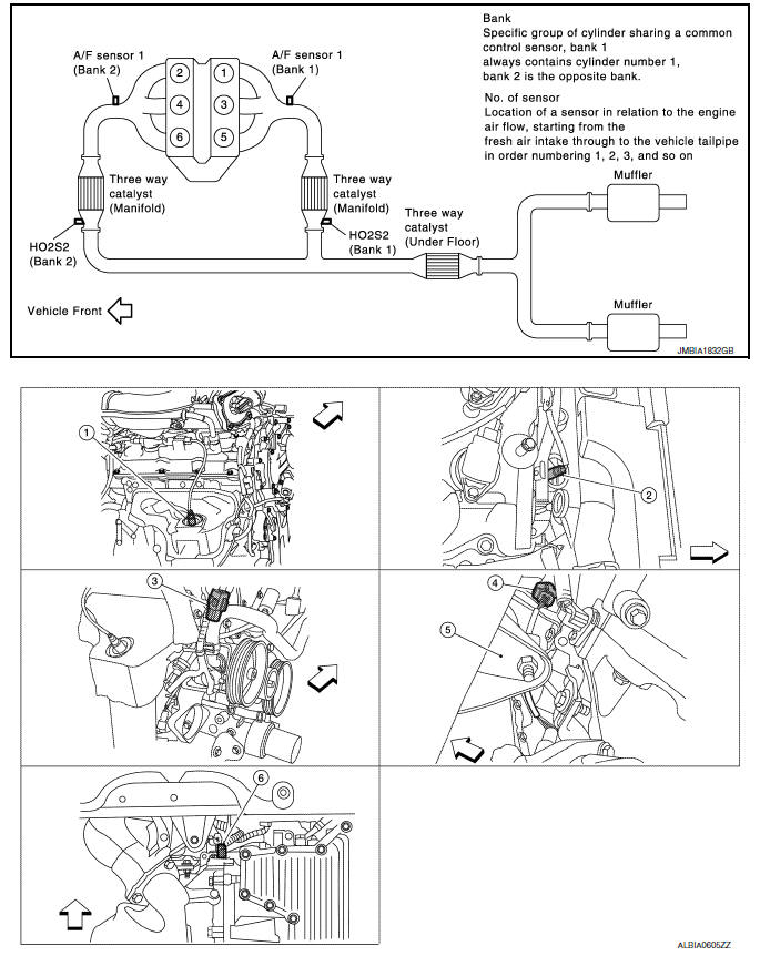
- A/F sensor 1 (bank 1) (view with engine removed)
- A/F sensor 1 (bank 2)
- HO2S2 (bank 1) harness connector (view with engine removed)
- HO2S2 (bank 2) harness connector
- Front engine mount
- Crankshaft position sensor (POS)
 : Vehicle front
- Electronic controlled engine mount control solenoid valve (view with engine cover removed)
- EVAP control system pressure sensor (view with rear suspension member removed)
- EVAP canister vent control valve
- EVAP canister
- Fuel injector harness connector (view with intake manifold collector removed)
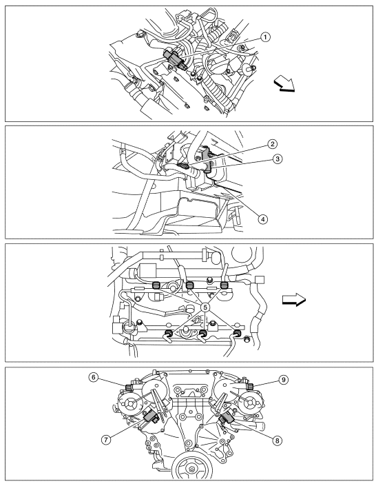
- Exhaust valve timing control magnet retarder (bank 1) (view with engine removed)
- Intake valve timing control solenoid valve (bank 1)
- Intake valve timing control solenoid valve (bank 2)
- Exhaust valve timing control magnet
retarder (bank 2)
 : Vehicle front
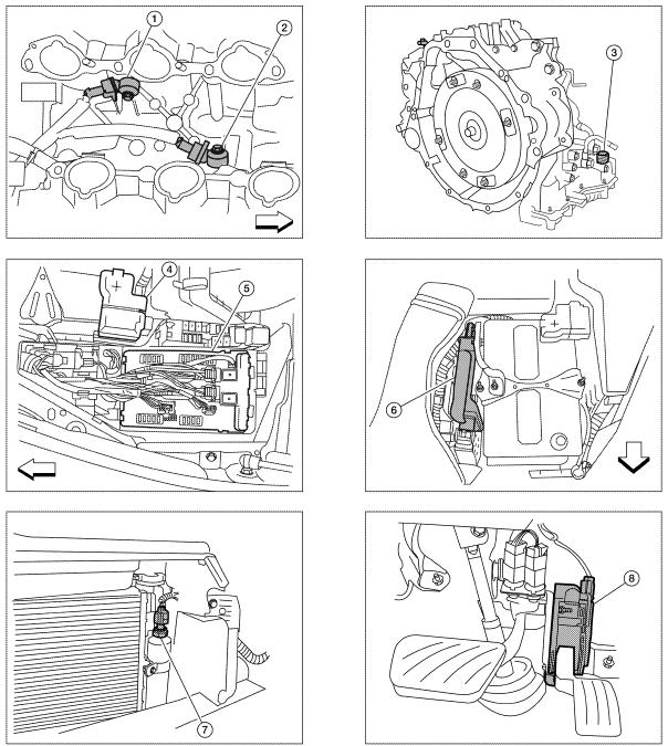
- Knock sensor (bank 2) (view with intake manifold removed)
- Knock sensor (bank 1)
- Transmission range switch (view with CVT removed)
- Battery
- IPDM E/R
- ECM
- Refrigerant pressure sensor (view with front grille removed)
- Accelerator pedal position sensor
 : Vehicle front
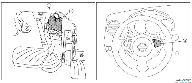
- Stop lamp switch
- ASCD brake switch
- ASCD steering switch
Component Description
Component Reference
- Accelerator pedal position sensor EC-467, "Description"
- Camshaft position sensor (PHASE) EC-300, "Description"
- Crankshaft position sensor (POS) EC-296, "Description"
- Engine coolant temperature sensor EC-201, "Description"
- Ignition signal EC-502, "Description"
- Knock sensor EC-293, "Description"
- Mass air flow sensor EC-183, "Description"
- TCM EC-397, "Description"
- Throttle position sensor
 Multiport fuel injection system
System Diagram
System Description
INPUT/OUTPUT SIGNAL CHART
*1: This sensor is not used to control the engine system under normal
conditions.
*2: This signal is sent to the ECM via the ...
 Air conditioning cut control
System Diagram
System Description
INPUT/OUTPUT SIGNAL CHART
*1: This signal is sent to the ECM via the CAN communication line.
*2: ECM determines the start signal status by the signals of ...
Other materials:
ECM branch line circuit
Diagnosis Procedure
1.CHECK CONNECTOR
Turn the ignition switch OFF.
Disconnect the battery cable from the negative
terminal.
Check the following terminals and connectors
for damage, bend and loose connection (unit side and connector
side).
&nb ...
M&A branch line circuit
Diagnosis Procedure
1.CHECK CONNECTOR
Turn the ignition switch OFF.
Disconnect the battery cable from the negative terminal.
Check the terminals and connectors of the combination meter for
damage, bend and loose connection
(unit side and connector side).
2.CHECK HARNESS FOR OPEN CI ...
Rear window defogger switch
Description
The rear window defogger is operated by turning the rear window defogger
switch ON.
Turns the indicator lamp in the rear window defogger switch ON
when operating the rear window defogger.
Component Function Check
1. CHECK REAR WINDOW DEFOGGER SWITCH FUNCTION
Check that t ...
Nissan Maxima Owners Manual
- Illustrated table of contents
- Safety-Seats, seat belts and supplemental restraint system
- Instruments and controls
- Pre-driving checks and adjustments
- Monitor, climate, audio, phone and voice recognition systems
- Starting and driving
- In case of emergency
- Appearance and care
- Do-it-yourself
- Maintenance and schedules
- Technical and consumer information
Nissan Maxima Service and Repair Manual

0.0085