Nissan Maxima Service and Repair Manual: Air conditioning cut control
System Diagram
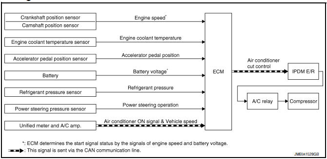
System Description
INPUT/OUTPUT SIGNAL CHART
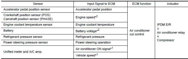
*1: This signal is sent to the ECM via the CAN communication line.
*2: ECM determines the start signal status by the signals of engine speed and
battery voltage.
SYSTEM DESCRIPTION
This system improves engine operation when the air conditioner is used.
Under the following conditions, the air conditioner is turned OFF.
- When the accelerator pedal is fully depressed.
- When cranking the engine.
- At high engine speeds.
- When the engine coolant temperature becomes excessively high.
- When operating power steering during low engine speed or low vehicle speed.
- When engine speed is excessively low.
- When refrigerant pressure is excessively low or high.
Component Parts Location
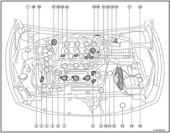
- Intake valve timing control solenoid valve (bank 1)
- Electronic controlled engine mount control solenoid valve
- Exhaust valve timing control magnet retarder (bank 2)
- Intake valve timing control solenoid valve (bank 2)
- Knock sensor (bank 1 and 2)
- Fuel injector (bank 2)
- Ignition coil (with power transistor) and spark plug (bank 2)
- Exhaust valve timing control position sensor (bank 2)
- Crankshaft position sensor (POS)
- . Engine coolant temperature sensor
- Camshaft position sensor (PHASE) (bank 2)
- . Transmission range switch
- Refrigerant pressure sensor
- ECM
- Battery current sensor
- Condenser-2
- EVAP canister purge volume control solenoid valve
- Mass air flow sensor (with intake air temperature sensor)
- Camshaft position sensor (PHASE) (bank 1)
- EVAP service port
- Power valve actuator 2
- Electric throttle control actuator
- Exhaust valve timing control position sensor (bank 1)
- Ignition coil (with power transistor) and spark plug (bank 1)
- Fuel injector (bank 1)
- VIAS control solenoid valve 1 and 2
- Power valve actuator 1
- Exhaust valve timing control magnet retarder (bank 1)
- Power steering pressure sensor
- Mas air flow sensor (with intake air temperature sensor)
- Air cleaner case
- Engine coolant temperature sensor (view with engine cover removed)
- EVAP canister purge volume control solenoid valve (view with engine cover removed)
- Power valve actuator 1 (view with engine cover removed)
- VIAS control solenoid valve 1
- VIAS control solenoid valve 2
- Power valve actuator 2
- Power steering pressure sensor
- Tie rod (RH)
- Camshaft position sensor (PHASE) (bank 1) (view with air cleaner case removed)
- Exhaust valve timing control position sensor (bank 1)
- Camshaft position sensor (PHASE) (bank 2) (view with air cleaner case removed)
- Exhaust valve timing control position sensor (bank 2)
- Engine oil temperature sensor
 : Vehicle front
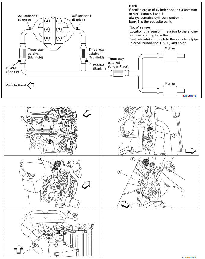
- A/F sensor 1 (bank 1) (view with engine removed)
- A/F sensor 1 (bank 2)
- HO2S2 (bank 1) harness connector (view with engine removed)
- HO2S2 (bank 2) harness connector
- Front engine mount 6. Crankshaft position sensor (POS)
 : Vehicle front
- Electronic controlled engine mount control solenoid valve (view with engine cover removed)
- EVAP control system pressure sensor (view with rear suspension member removed)
- EVAP canister vent control valve
- EVAP canister
- Fuel injector harness connector (view with intake manifold collector removed)
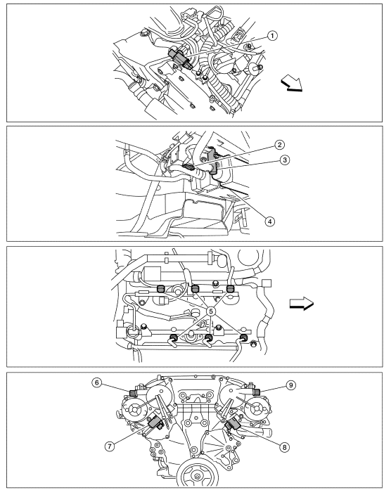
- Exhaust valve timing control magnet retarder (bank 1) (view with engine removed)
- Intake valve timing control solenoid valve (bank 1)
- Intake valve timing control solenoid valve (bank 2)
- Exhaust valve timing control magnet
retarder (bank 2)
 : Vehicle front
- Knock sensor (bank 2) (view with intake manifold removed)
- Knock sensor (bank 1)
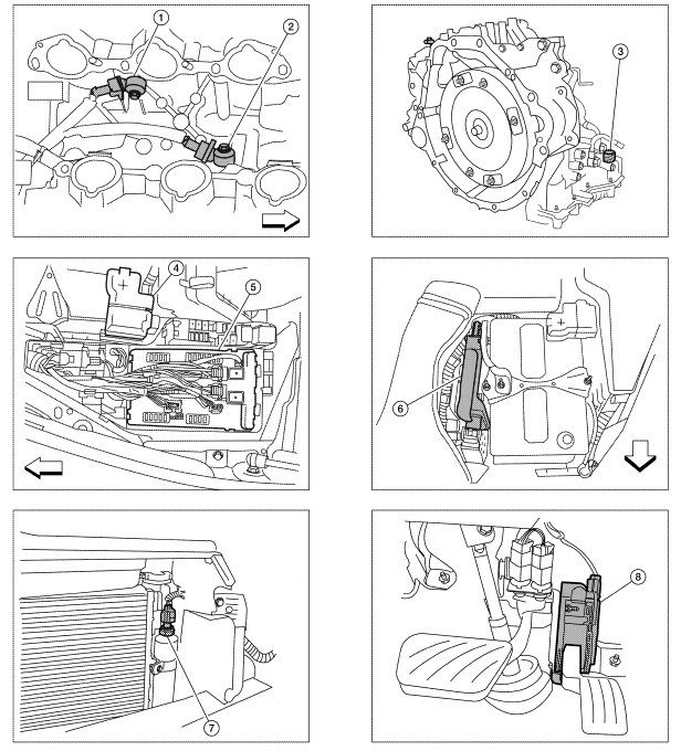
- Transmission range switch (view with CVT removed)
- Battery
- IPDM E/R
- ECM
- Refrigerant pressure sensor (view with front grille removed)
- Accelerator pedal position sensor
 : Vehicle front
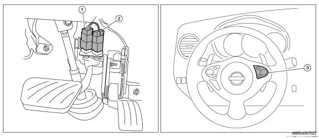
- Stop lamp switch
- ASCD brake switch
- ASCD steering switch
Component Description
Component Reference
- Accelerator pedal position sensor EC-467, "Description"
- Camshaft position sensor (PHASE) EC-300, "Description"
- Crankshaft position sensor (POS) EC-296, "Description"
- Engine coolant temperature sensor EC-201, "Description"
- Power steering pressure sensor EC-386, "Description"
- Refrigerant pressure sensor
 Electric ignition system
System Diagram
System Description
INPUT/OUTPUT SIGNAL CHART
*1: This signal is sent to the ECM via the CAN communication line.
*2: ECM determines the start signal status by the signals of ...
 Automatic speed control device (ASCD)
System Diagram
System Description
INPUT/OUTPUT SIGNAL CHART
*: This signal is sent to the ECM via the CAN communication line
BASIC ASCD SYSTEM
Refer to Owner's Manual for ASCD operating i ...
Other materials:
ECM branch line circuit
Diagnosis Procedure
1.CHECK CONNECTOR
Turn the ignition switch OFF.
Disconnect the battery cable from the negative terminal.
Check the following terminals and connectors for damage, bend and
loose connection (unit side and connector
side).
- Models without automatic drive positione ...
Parking brake shoe
Exploded View
Back plate
Parking brake shoe (front)
Adjuster
Adjuster spring
Return spring
Anti-rattle spring
Retainer
Anti-rattle pin
Toggle lever
Parking brake shoe (rear)
Front
Apply PBC (Poly Butyl Cuprysil)
grease or silicone based grease
Removal ...
Wiring diagram
ELECTRONICALLY CONTROLLED POWER STEERING SYSTEM
Wiring Diagram
...
Nissan Maxima Owners Manual
- Illustrated table of contents
- Safety-Seats, seat belts and supplemental restraint system
- Instruments and controls
- Pre-driving checks and adjustments
- Monitor, climate, audio, phone and voice recognition systems
- Starting and driving
- In case of emergency
- Appearance and care
- Do-it-yourself
- Maintenance and schedules
- Technical and consumer information
Nissan Maxima Service and Repair Manual

0.0066