Nissan Maxima Service and Repair Manual: Hydraulic line
Exploded View
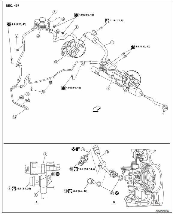
- High pressure hose
- Suction hose
- Reservoir tank bracket
- Reservoir tank
- Oil pump assembly
- Steering gear assembly
- Low pressure piping
- Eye bolt
- High pressure piping
- Copper sealing washers
- Eye bolt
- Copper sealing washers
- Power steering pressure sensor
- High pressure hose piping
- Power steering fluid cooler
- O-ring
 Front
Front - View A
- View B
Removal and Installation
CAUTION:
- Securely insert harness connector to pressure sensor.
- Do not reuse O-rings or copper sealing washers.
NOTE: When removing components such as hoses, tubes/lines, etc., cap or plug openings to prevent fluid from spilling.
REMOVAL
Refer to ST-29, "Exploded View" for removal.
INSTALLATION
- Insert hose securely until it contacts tube spool.
CAUTION: Do not use lubricant on hose or fitting.
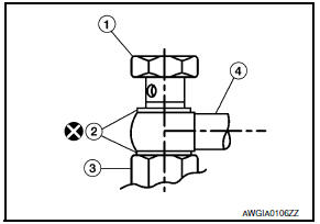
- Install eye-bolt (1), copper sealing washers (2) and eye-joint (assembled to high-pressure hose) (4) onto oil pump assembly (3), and temporarily tighten the eye-bolt, then tighten it to the specified torque.
CAUTION: Do not reuse copper sealing washers.
 Power steering oil pump
Exploded View
Rear bracket
Power steering oil pump assembly
Front bracket
Removal and Installation
NOTE: When removing components such as
hoses, tubes/lines, etc., cap or plug open ...

Other materials:
Extending engine run time
The remote start feature can be extended one
time by performing the steps listed in "Remote
starting the vehicle" in this section. Run time will
be calculated as follows:
The first 10 minute run time will start when
the remote start function is performed.
The second 10 minutes will start ...
Vehicle speed signal circuit
Description
Combination meter sends vehicle speed signal to power steering control unit.
Diagnosis Procedure
1.PERFORM COMBINATION METER SELF-DIAGNOSIS
Perform combination meter self-diagnosis.
2.CHECK HARNESS BETWEEN COMBINATION METER AND POWER STEERING CONTROL UNIT FOR
OPEN
Turn the ...
Precaution
PRECAUTIONS
Precaution for Supplemental Restraint System (SRS) "AIR BAG" and "SEAT
BELT
PRE-TENSIONER"
The Supplemental Restraint System such as "AIR BAG" and "SEAT BELT
PRE-TENSIONER", used along
with a front seat belt, helps to reduce the risk or severity of injury to ...
Nissan Maxima Owners Manual
- Illustrated table of contents
- Safety-Seats, seat belts and supplemental restraint system
- Instruments and controls
- Pre-driving checks and adjustments
- Monitor, climate, audio, phone and voice recognition systems
- Starting and driving
- In case of emergency
- Appearance and care
- Do-it-yourself
- Maintenance and schedules
- Technical and consumer information
Nissan Maxima Service and Repair Manual

0.0057