Nissan Maxima Service and Repair Manual: Power door lock system
Wiring Diagram
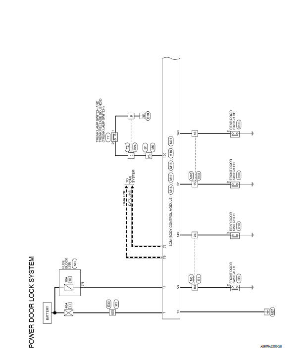
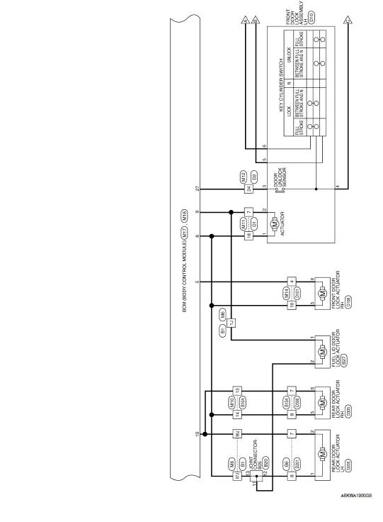
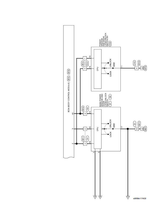
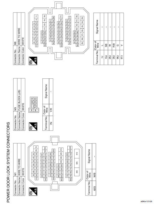
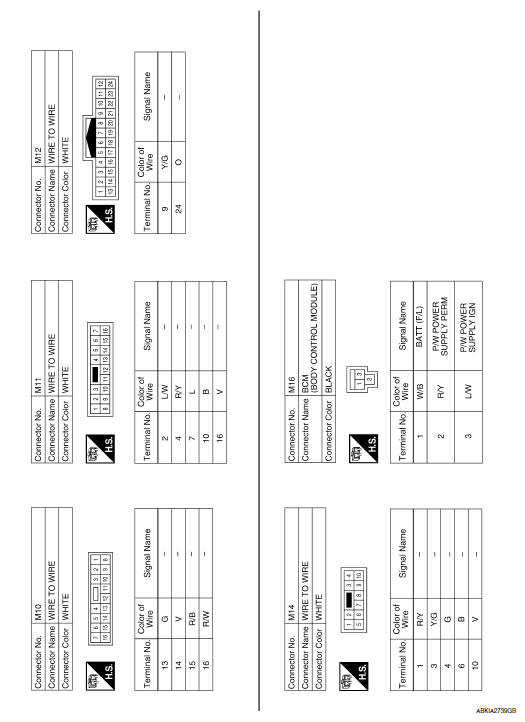
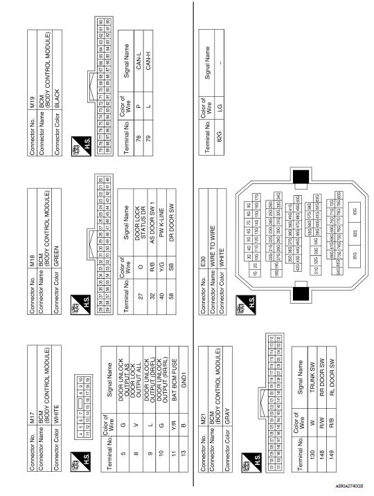
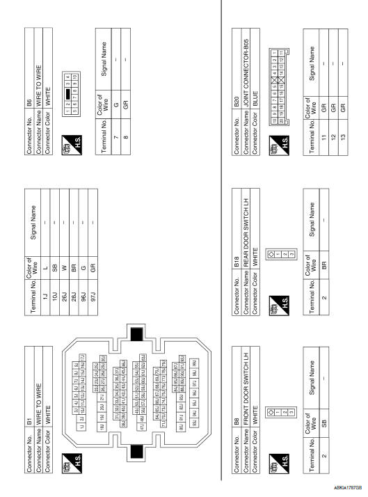
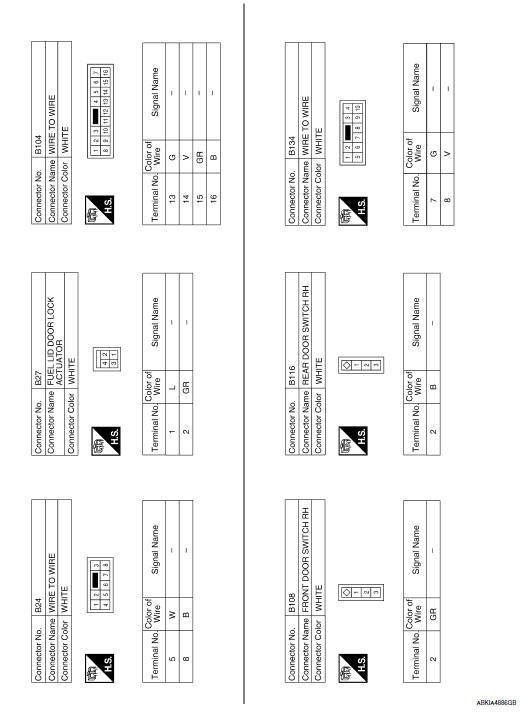
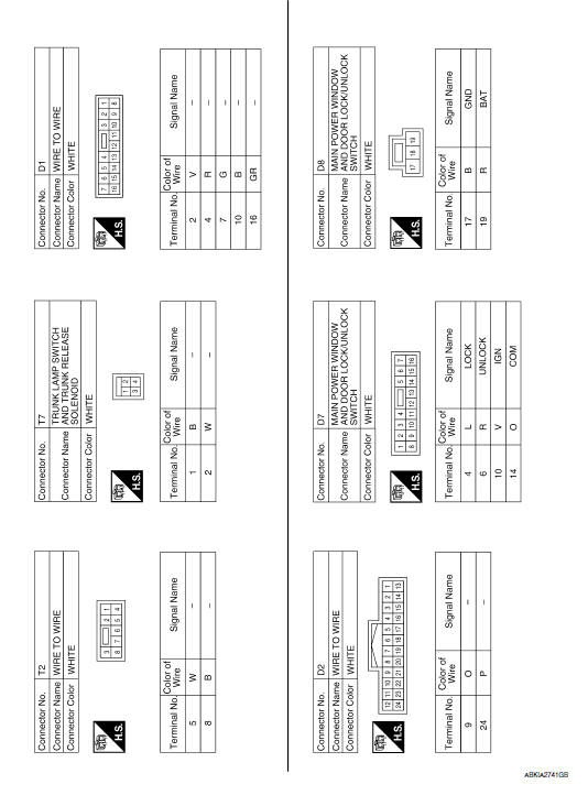
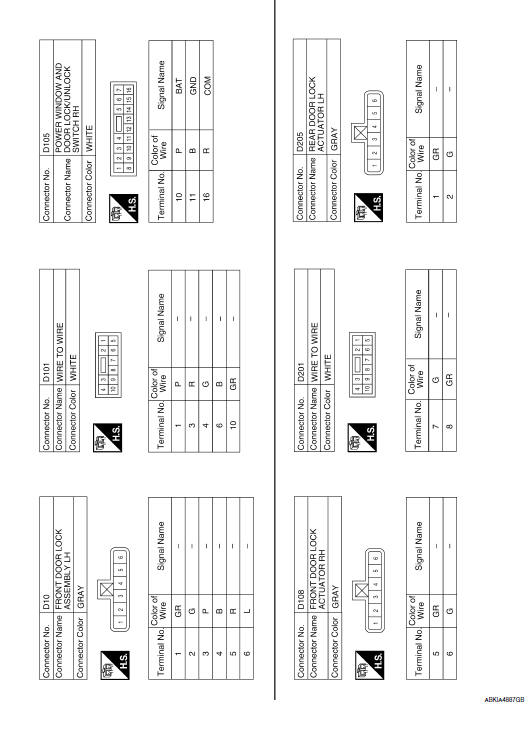
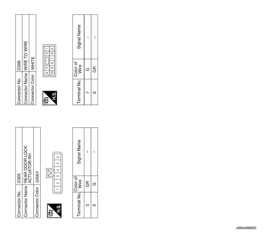
 Wiring diagram
...
 Intelligent key system
Wiring Diagram
...
Other materials:
Fuel level sensor signal circuit
Description
The fuel level sensor unit and fuel pump (fuel level
sensor) detects the approximate fuel level in the fuel tank
and transmits the fuel level signal to the combination meter.
Component Function Check
1.COMBINATION METER INPUT SIGNAL
Select "METER/M&A" on CONSULT.
...
Rear seat
Exploded View - Fixed Seatback
Headrest
Headrest holder (free)
Headrest holder (locked)
Bumper
Seatback assembly
Seatback trim
Seatback pad
Seat cushion trim
Seat cushion pad
Seat cushion wire cover
Seat cushion lock
Seat cushion assembly
Removal and Installati ...
Auto light system
System Diagram
System Description
BCM (Body Control Module) controls auto light operation according to
signals from optical sensor, lighting switch and ignition switch.
IPDM E/R (Intelligent Power Distribution Module Engine Room) operates
parking, license plate, tail, front fog lamps ...
Nissan Maxima Owners Manual
- Illustrated table of contents
- Safety-Seats, seat belts and supplemental restraint system
- Instruments and controls
- Pre-driving checks and adjustments
- Monitor, climate, audio, phone and voice recognition systems
- Starting and driving
- In case of emergency
- Appearance and care
- Do-it-yourself
- Maintenance and schedules
- Technical and consumer information
Nissan Maxima Service and Repair Manual

0.0065