Nissan Maxima Service and Repair Manual: Audio unit
Removal and Installation
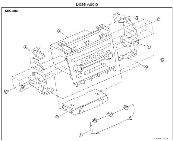
- Audio unit brackets (LH/RH)
- A/C auto amp.
- Cluster lid C lower
- Audio unit
 Clip
Clip
 Pawl
Pawl
REMOVAL
- Disconnect the battery negative terminal. Refer to PG-67, "Removal and Installation (Battery)".
- Remove the cluster lid D. Refer to IP-11, "Removal and Installation".
- Remove the cluster lid C lower finisher (1).
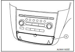
 : Pawl
 : Clip
- Remove the audio unit screws (A) and the cluster lid C screws (B).
- Pull out the audio unit, disconnect the connectors and remove the audio unit.
INSTALLATION
Installation is in the reverse order of removal.

 Audio display unit
Removal and Installation
Audio display unit
Audio & A/C display unit bracket
A/C display unit
Front cover
REMOVAL
Disconnect the battery negative terminal. Refer to PG-68, ...
Other materials:
Water pump
Exploded View
Water pump
O-rings
Timing chain tensioner
Intake valve timing control solenoid
valve cover (RH) (bank 1)
Water pump cover
Removal and Installation
WARNING:
Do not remove the radiator cap when the engine is hot. Serious burns could occur
from high pressure
co ...
C1105, C1106, C1107, C1108 wheel sensor
DTC Logic
DTC DETECTION LOGIC
DTC CONFIRMATION PROCEDURE
1.CHECK SELF DIAGNOSTIC RESULT
With CONSULT.
Start engine and drive vehicle at approximately 21 km/h (13 MPH)
or more for approximately 5 minutes.
Perform self diagnostic result
Diagnosis Procedure
CAUTION:
Do not check ...
Microphone
Removal and Installation
REMOVAL
Remove the front room/map lamp assembly. Refer to INL-84, "Removal and
Installation".
Detach the microphone connector (A).
Remove the front room/map lamp covers (1), then remove the
map lamp assembly cover (2).
Release t ...
Nissan Maxima Owners Manual
- Illustrated table of contents
- Safety-Seats, seat belts and supplemental restraint system
- Instruments and controls
- Pre-driving checks and adjustments
- Monitor, climate, audio, phone and voice recognition systems
- Starting and driving
- In case of emergency
- Appearance and care
- Do-it-yourself
- Maintenance and schedules
- Technical and consumer information
Nissan Maxima Service and Repair Manual

0.0068