Nissan Maxima Service and Repair Manual: Oil cooler
Removal and Installation
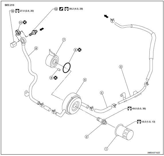
- Oil filter
- Oil cooler bolt
- Water pipe
- Water hose
- Oil cooler
- O-ring
- Oil pan
- Water pipe
- Relief valve
- Water drain plug
- Copper gasket
- Water connector
 Engine coolant flow
WARNING: Be careful not to get burned, engine coolant and engine oil may be hot.
CAUTION:
- When removing oil cooler, prepare a shop cloth to absorb any engine oil leakage or spillage.
- Completely wipe off any engine oil that adheres to the engine and the vehicle.
NOTE: When removing components such as hoses, tubes/lines, etc., cap or plug openings to prevent fluid from spilling.
REMOVAL
- Remove the engine under cover. Refer to EXT-15, "Exploded View".
- Remove the RH wheel and tire. Refer to WT-60, "Adjustment".
- Remove the front fender protector side cover (RH). Refer to EXT-23, "Exploded View".
- Drain engine coolant. CAUTION: Do not spill coolant on the drive belt.
- Disconnect water hoses from oil cooler.
- Remove the oil filter. Refer to LU-10, "Removal and Installation".
- Remove oil cooler.
INSPECTION AFTER REMOVAL
- Check oil cooler for cracks.
- Check oil cooler for clogging by blowing through coolant inlet. If necessary, replace oil cooler.
Oil Pressure Relief Valve
Inspect oil pressure relief valve for movement, cracks and breaks by pushing the ball. If replacement is necessary, remove valve by prying it out with a suitable tool. Install a new valve in place by tapping it.
INSTALLATION
Installation is in the reverse order of removal.
CAUTION:
- Do not reuse O-ring.
- Do not reuse copper gasket.
- When installing the oil cooler, align the oil cooler stopper with the stopper of the oil pan.
- Replace oil pressure relief valve after every removal.
INSPECTION AFTER INSTALLATION
Start engine and check for engine oil and coolant leaks. Repair as necessary.
 Oil pump
Removal and Installation
REMOVAL
Remove the engine from the vehicle. Refer to EM-103, "Removal and
Installation".
Remove the upper oil pan. Refer to EM-37, "Removal and
Instal ...
 Service data and specifications (SDS)
Oil Pressure
Regulator Valve
Oil Pump
Oil Capacity
...
Other materials:
Switch operation
Type A (if so equipped)
The windshield wiper and washer operates when
the ignition switch is placed in the ON position.
Push the lever down to operate the wiper at the
following speed:
Intermittent (INT) or (AUTO) - intermittent
operation can be adjusted by turning the
knob A .
L ...
Cleaning
If your windshield is not clear after using the
windshield-washer or if a wiper blade chatters
when running, wax or other material may be on
the blade or windshield.
Clean the outside of the windshield with a washer
solution or a mild detergent. Your windshield is
clean if beads do not form ...
Power supply and ground circuit
BCM (BODY CONTROL MODULE)
BCM (BODY CONTROL MODULE) : Diagnosis Procedure
1. CHECK FUSE AND FUSIBLE LINK
Check if the following BCM fuses or fusible link are blown.
2. CHECK POWER SUPPLY CIRCUIT
Turn ignition switch OFF.
Disconnect BCM.
Check voltage between BCM harness connector and ...
Nissan Maxima Owners Manual
- Illustrated table of contents
- Safety-Seats, seat belts and supplemental restraint system
- Instruments and controls
- Pre-driving checks and adjustments
- Monitor, climate, audio, phone and voice recognition systems
- Starting and driving
- In case of emergency
- Appearance and care
- Do-it-yourself
- Maintenance and schedules
- Technical and consumer information
Nissan Maxima Service and Repair Manual

0.0058