Nissan Maxima Service and Repair Manual: Bluetooth control unit
Reference Value
TERMINAL LAYOUT
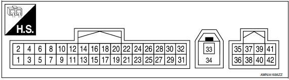
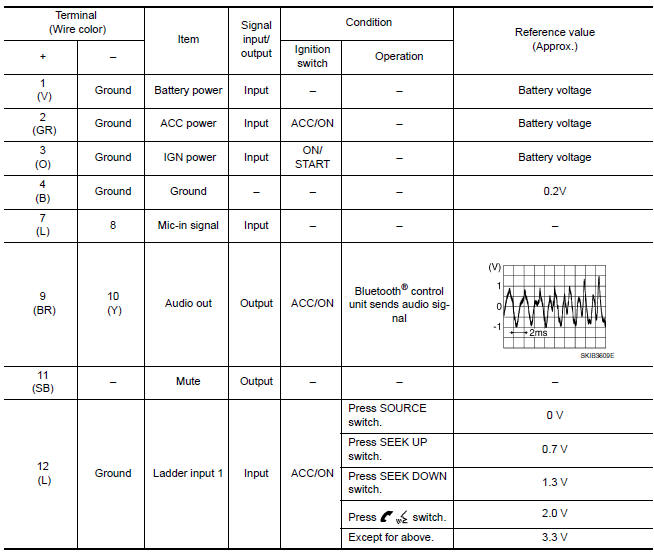
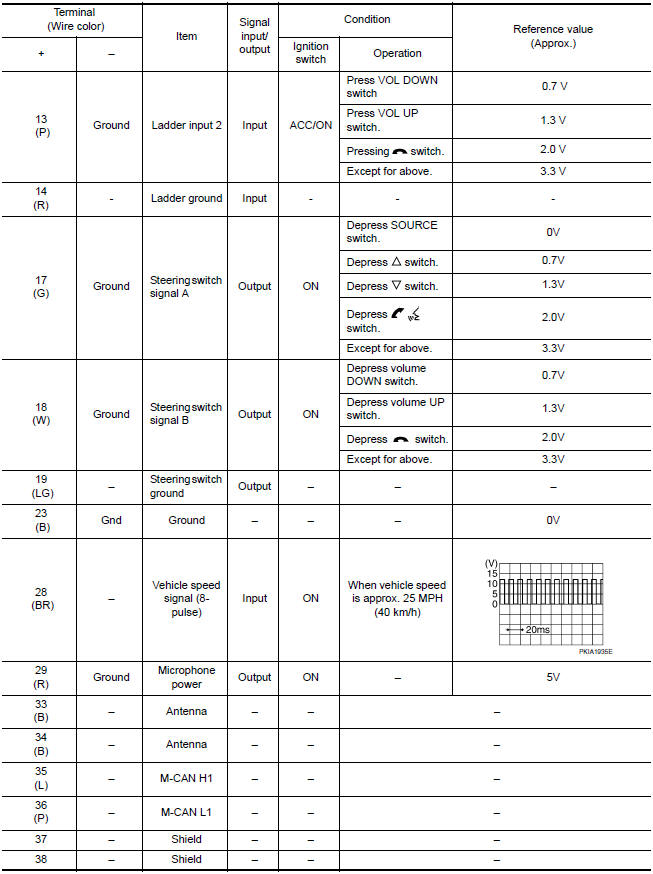
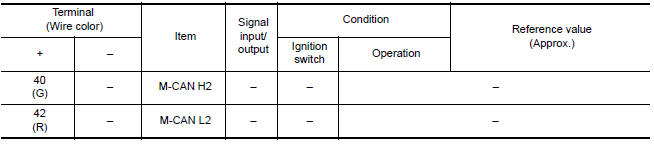
PHYSICAL VALUES
 Subwoofer AMP
Reference Value
TERMINAL LAYOUT
PHYSICAL VALUES
...
 Wiring diagram
MONOCHROME DISPLAY
Wiring Diagram - Without BOSE Audio system
...
Other materials:
Precaution
PRECAUTIONS
Precaution for Supplemental Restraint System (SRS) "AIR BAG" and
"SEAT BELT PRE-TENSIONER"
The Supplemental Restraint System such as "AIR BAG" and "SEAT BELT
PRE-TENSIONER", used along with a front seat belt, helps to reduce the risk
or severity of injury to the driver and front ...
Brake precautions
The brake system has two separate hydraulic
circuits. If one circuit malfunctions, you will still
have braking at two wheels.
Vacuum assisted brakes
The brake booster aids braking by using engine
vacuum. If the engine stops, you can stop the
vehicle by depressing the brake pedal. However,
gre ...
Replacing
Replace the wiper blades if they are worn.
To replace the windshield wiper blades, follow
the procedure below:
1. Lift the wiper arm away from the windshield.
2. Push the release tab B .
3. Move the wiper blade A down and remove.
4. Insert the new wiper blade onto the wiper
arm unti ...
Nissan Maxima Owners Manual
- Illustrated table of contents
- Safety-Seats, seat belts and supplemental restraint system
- Instruments and controls
- Pre-driving checks and adjustments
- Monitor, climate, audio, phone and voice recognition systems
- Starting and driving
- In case of emergency
- Appearance and care
- Do-it-yourself
- Maintenance and schedules
- Technical and consumer information
Nissan Maxima Service and Repair Manual

0.0068