Nissan Maxima Service and Repair Manual: Subwoofer AMP
Reference Value
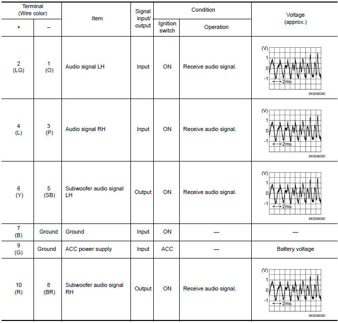
TERMINAL LAYOUT

PHYSICAL VALUES
 Display unit
Reference Values
TERMINAL LAYOUT
PHYSICAL VALUES
...
 Bluetooth control unit
Reference Value
TERMINAL LAYOUT
PHYSICAL VALUES
...
Other materials:
Magnet clutch
Description
SYSTEM DESCRIPTION
A/C auto amp. controls A/C compressor operation by ambient temperature and
signal from ECM.
Low Temperature Protection Control
A/C auto amp. will turn the A/C compressor ON or OFF as determined
by a signal detected by ambient sensor.
When ambient temper ...
Service data and specifications (SDS)
SERVICE DATA AND SPECIFICATIONS (SDS)
General Specifications
Brake Pedal
Check Valve
Brake Booster
Front Disc Brake
Rear Disc Brake
...
Clip list
Descriptions for Clips
Replace any clips which are damaged during removal or installation.
...
Nissan Maxima Owners Manual
- Illustrated table of contents
- Safety-Seats, seat belts and supplemental restraint system
- Instruments and controls
- Pre-driving checks and adjustments
- Monitor, climate, audio, phone and voice recognition systems
- Starting and driving
- In case of emergency
- Appearance and care
- Do-it-yourself
- Maintenance and schedules
- Technical and consumer information
Nissan Maxima Service and Repair Manual

© 2017-2026 Copyright www.nimainfo.com
0.006
0.006