Nissan Maxima Service and Repair Manual: Display unit
Reference Values
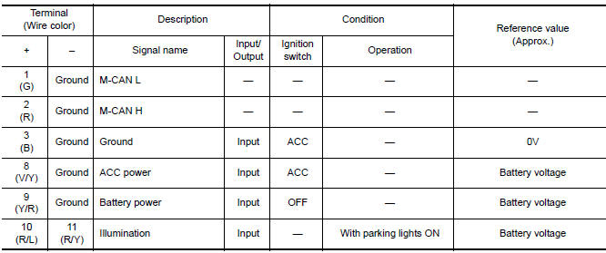
TERMINAL LAYOUT
PHYSICAL VALUES
 Audio unit
Reference Value
TERMINAL LAYOUT
PHYSICAL VALUES
...
 Subwoofer AMP
Reference Value
TERMINAL LAYOUT
PHYSICAL VALUES
...
Other materials:
U1244 GPS antenna
DTC Logic
Diagnosis Procedure
1.GPS ANTENNA CHECK
Inspect GPS antenna and antenna feeder for damage or poor connection.
2.CHECK AV CONTROL UNIT VOLTAGE
Turn ignition switch ON.
Check voltage between AV control unit connector M165 terminal
105 and ground.
...
Heating (A/C OFF)
The air conditioner does not activate. When you
need to heat only, use this mode.
1. Press the AUTO button.
2. Turn the temperature control dial to set the
desired temperature.
The temperature of the passenger compartment
will be maintained automatically. Air
flow distribution and fa ...
Power supply and ground circuit
CLIMATE CONTROLLED SEAT CONTROL UNIT
CLIMATE CONTROLLED SEAT CONTROL UNIT : Diagnosis Procedure
Regarding Wiring Diagram information, refer to SE-44, "Wiring Diagram".
1.CHECK FUSES
2.CHECK BATTERY POWER SUPPLY CIRCUIT
Turn ignition switch OFF.
Disconnect climate controlled seat control ...
Nissan Maxima Owners Manual
- Illustrated table of contents
- Safety-Seats, seat belts and supplemental restraint system
- Instruments and controls
- Pre-driving checks and adjustments
- Monitor, climate, audio, phone and voice recognition systems
- Starting and driving
- In case of emergency
- Appearance and care
- Do-it-yourself
- Maintenance and schedules
- Technical and consumer information
Nissan Maxima Service and Repair Manual

0.0065