Nissan Maxima Service and Repair Manual: Center console assembly
Exploded View
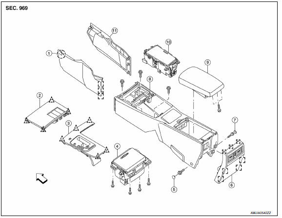
- Center console side finisher (LH)
- Center console finisher
- CVT finisher
- Center console storage bin
- Center console screw cover (LH)
- Center console rear finisher
- Center console screw cover (RH)
- Center console
- Center console lid assembly
- Cup holder
- Center console side finisher (RH)
 Front
Front
 Clip
Clip
 Metal clip
 Pawl
Pawl
Removal and Installation
REMOVAL
CAUTION: Be careful not to scratch center console finishers and other parts.
- Remove the center console side finishers (LH/RH).
- Disconnect the center console harness connectors (A).
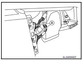
- Remove the CVT shift selector handle. Refer to TM-170, "Removal and Installation".
- Remove the CVT finisher, using a suitable tool and while disconnecting necessary connectors.
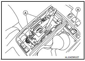
- Remove the center console screws (A).
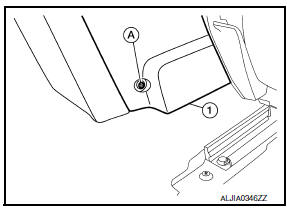
- Position the front seats forward (LH/RH).
- Remove the center console screw covers (LH/RH) and the rear center console screw (A) from each side of the rear of the center console assembly (1).
- Remove the center console assembly (1).
INSTALLATION
Installation is in the reverse order of removal.
 Steering column covers
Removal and Installation
MANUAL TILT
Removal
Remove the steering column cover screw finishers (1) and then
remove the screws.
Remove the steering column upper cover (2).
Remove the stee ...
 Cluster lid A
Removal and Installation
REMOVAL
Using a suitable tool, gently remove the instrument side finisher
LH (1).
Remove the instrument lower panel LH (1).
Open the fuse block cover and rem ...
Other materials:
Basic inspection
DIAGNOSIS AND REPAIR WORK FLOW
Work Flow
OVERALL SEQUENCE
DETAILED FLOW
1.GET INFORMATION FOR SYMPTOM
Get detailed information from the customer about the symptom (the condition
and the environment when the
incident/malfunction occurred).
2.CONFIRM THE SYMPTOM
Try to confirm the sympt ...
Basic inspection
DIAGNOSIS AND REPAIR WORK FLOW
WITH COLOR DISPLAY
WITH COLOR DISPLAY : How to Perform Trouble Diagnosis For Quick And
Accurate Repair
WORK FLOW
1.LISTEN TO CUSTOMER COMPLAINT
Interview the customer to obtain as much information as possible about the
conditions and environment under which th ...
B2605 transmission range switch
Description
BCM confirms the shift position with the following 4
signals.
CVT selector lever
Transmission range switch
P position signal from IPDM E/R (CAN)
P position signal from TCM (CAN)
DTC Logic
DTC DETECTION LOGIC
NOTE:
I ...
Nissan Maxima Owners Manual
- Illustrated table of contents
- Safety-Seats, seat belts and supplemental restraint system
- Instruments and controls
- Pre-driving checks and adjustments
- Monitor, climate, audio, phone and voice recognition systems
- Starting and driving
- In case of emergency
- Appearance and care
- Do-it-yourself
- Maintenance and schedules
- Technical and consumer information
Nissan Maxima Service and Repair Manual

0.0057