Nissan Maxima Service and Repair Manual: Symptom diagnosis
REFRIGERATION SYSTEM SYMPTOMS
WITH COLOR DISPLAY
WITH COLOR DISPLAY : Trouble Diagnoses for Abnormal Pressure
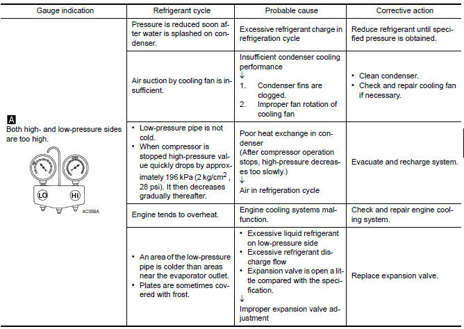
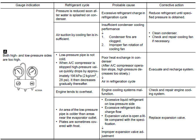
Whenever system′s high and/or low side pressure is abnormal, diagnose using a manifold gauge. The marker above the gauge scale in the following tables indicates the standard (usual) pressure range. Since the standard (usual) pressure, however, differs from vehicle to vehicle, refer to above table (Ambient air temperatureto- operating pressure table).
Both High- and Low-pressure Sides are Too High
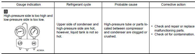
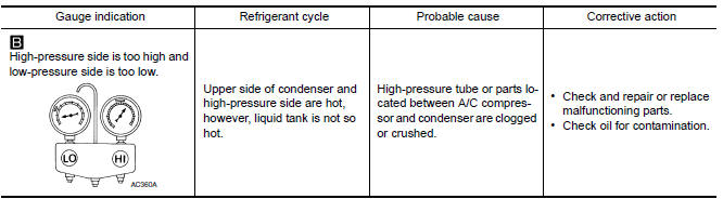
High-pressure Side is Too High and Low-pressure Side is Too Low
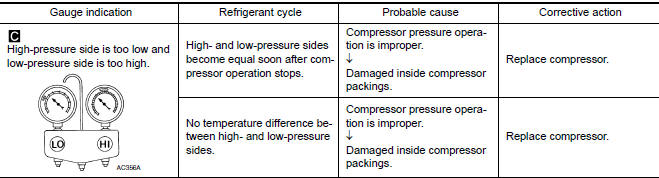
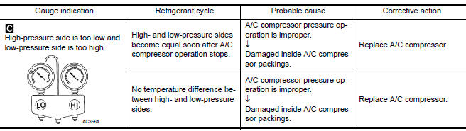
High-pressure Side is Too Low and Low-pressure Side is Too Hig
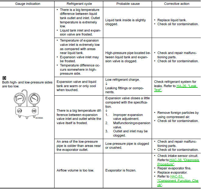
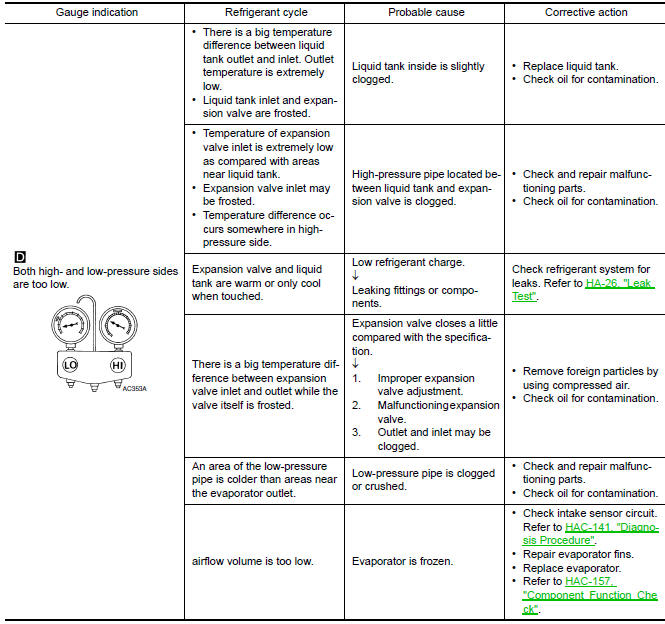
Both High- and Low-pressure Sides are Too Low
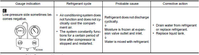
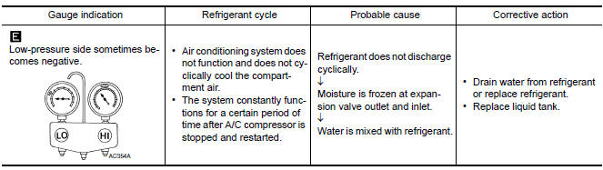
Low-pressure Side Sometimes Becomes Negative
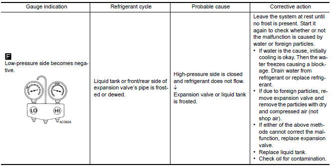
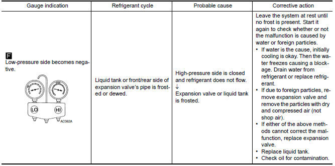
Low-pressure Side Becomes Negative
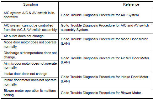
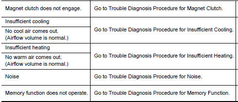
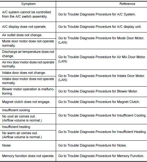
WITH COLOR DISPLAY : Symptom Matrix Chart
WITH MONOCHROME DISPLAY
WITH MONOCHROME DISPLAY : Trouble Diagnoses for Abnormal Pressure
Whenever system′s high and/or low side pressure is abnormal, diagnose using a manifold gauge. The marker above the gauge scale in the following tables indicates the standard (usual) pressure range. Since the standard (usual) pressure, however, differs from vehicle to vehicle, refer to above table (Ambient air temperatureto- operating pressure table).
Both High- and Low-pressure Sides are Too High
High-pressure Side is Too High and Low-pressure Side is Too Low
High-pressure Side is Too Low and Low-pressure Side is Too High
Both High- and Low-pressure Sides are Too L
Low-pressure Side Sometimes Becomes Negative
Low-pressure Side Becomes Nega
WITH MONOCHROME DISPLAY : Symptom Matrix Chart
 Basic inspection
DIAGNOSIS AND REPAIR WORK FLOW
WITH COLOR DISPLAY
WITH COLOR DISPLAY : How to Perform Trouble Diagnosis For Quick And
Accurate Repair
WORK FLOW
1.LISTEN TO CUSTOMER COMPLAINT
Interview the cust ...

Other materials:
Bose speaker AMP
Reference Values
TERMINAL LAYOUT
PHYSICAL VALUES
...
Satellite radio tuner
Reference Value
PHYSICAL VALUES
...
Power supply and ground circuit
Diagnosis Procedure
1. CHECK FUSE AND FUSIBLE LINK
Check if the following BCM fuses or fusible link are blown
2. CHECK POWER SUPPLY CIRCUIT
Turn ignition switch OFF.
Disconnect BCM.
Check voltage between BCM harness connector and ground.
3. CHECK GROUND CIRCUIT
Check contin ...
Nissan Maxima Owners Manual
- Illustrated table of contents
- Safety-Seats, seat belts and supplemental restraint system
- Instruments and controls
- Pre-driving checks and adjustments
- Monitor, climate, audio, phone and voice recognition systems
- Starting and driving
- In case of emergency
- Appearance and care
- Do-it-yourself
- Maintenance and schedules
- Technical and consumer information
Nissan Maxima Service and Repair Manual

0.0061