Nissan Maxima Service and Repair Manual: AV branch line circuit
Diagnosis Procedure
1.CHECK CONNECTOR
- Turn the ignition switch OFF.
- Disconnect the battery cable from the negative terminal.
- Check the terminals and connectors of the AV control unit for damage, bend and loose connection (unit side and connector side).
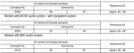
2.CHECK HARNESS FOR OPEN CIRCUIT
- Disconnect the connector of AV control unit.
- Check the resistance between the AV control unit harness connector
terminals.
- Models with BOSE audio system - without navigation system
3.CHECK POWER SUPPLY AND GROUND CIRCUIT
Check the power supply and the ground circuit of the AV control unit. Refer to the following.
- Models without BOSE audio with color display: AV-231, "AV CONTROL UNIT : Diagnosis Procedure"
- Models with BOSE audio with color display: AV-388, "AV CONTROL UNIT : Diagnosis Procedure"
- Models with BOSE audio with color display with navigation system: AV-571, "AV CONTROL UNIT : Diagnosis Procedure"
 M&A branch line circuit
Diagnosis Procedure
1.CHECK CONNECTOR
Turn the ignition switch OFF.
Disconnect the battery cable from the negative terminal.
Check the terminals and connectors of the combination meter for
...
 HVAC branch line circuit
Diagnosis Procedure
1.CHECK CONNECTOR
Turn the ignition switch OFF.
Disconnect the battery cable from the negative terminal.
Check the terminals and connectors of the A/C auto amp. for
dam ...
Other materials:
Rear bumper
Exploded View
Rear bumper supports (RH/LH)
Rear bumper reinforcement
Rear energy absorber
Side bracket (RH/LH)
Rear bumper fascia
Removal and Installation
REMOVAL
Remove trunk floor carpet, side finishers, and rear finisher.
Refer to EXT-31, "Exploded View".
Remove the r ...
Performance test
Inspection
INSPECTION PROCEDURE
Connect recovery/recycling/recharging equipment (for HFC-134a) or
manifold gauge.
Start the engine, and set to the following condition.
Maintain test condition until A/C system becomes stable. (Approximately
10 minutes)
Check that test results ...
Precaution
Precaution for Supplemental Restraint System (SRS) "AIR BAG" and "SEAT
BELT
PRE-TENSIONER"
The Supplemental Restraint System such as "AIR BAG" and "SEAT BELT PRE-TENSIONER",
used along
with a front seat belt, helps to reduce the risk or severity of injury to the
driver ...
Nissan Maxima Owners Manual
- Illustrated table of contents
- Safety-Seats, seat belts and supplemental restraint system
- Instruments and controls
- Pre-driving checks and adjustments
- Monitor, climate, audio, phone and voice recognition systems
- Starting and driving
- In case of emergency
- Appearance and care
- Do-it-yourself
- Maintenance and schedules
- Technical and consumer information
Nissan Maxima Service and Repair Manual

0.0067