Nissan Maxima Service and Repair Manual: Audio system
SYSTEM DESCRIPTION
AUDIO SYSTEM
System Diagram
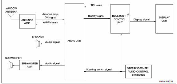
System Description
AUDIO SYSTEM
The audio system consists of the following components
- Audio unit
- Display unit
- Bluetooth control unit
- Window antenna
- Steering wheel audio control switches
- Front door speakers
- Tweeters
- Rear door speakers
- Subwoofer amp.
- Subwoofers
When the audio system is on, radio signals are received by the window antenna. The audio unit then sends audio signals to the front door speakers, tweeters, rear door speakers, subwoofer amp. and subwoofers.
Refer to Owner's Manual for audio system operating instructions.
Component Parts Location
- Tweeter LH M143
- Display unit M109
- Tweeter RH M144
- Audio unit M133, M147
- Steering wheel audio control switches 6. Front door speaker LH D3 RH D103
- Rear door speaker LH D209 RH D309
- Subwoofers (view of underside of parcel shelf) LH B16 RH B17
- Bluetooth control unit B125, B126, B130
- Subwoofer amp. B21 11. Microphone R7
Component Description
| Part name | Description |
| Audio unit | Controls audio and AUX IN system functions |
| Steering wheel audio control switches |
|
| Front door speakers |
|
| Tweeters |
|
| Rear door speakers |
|
| Bluetooth control unit |
|
| Display unit |
|
| Subwoofer amp |
|
| Subwoofers |
|
 Diagnosis and repair workflow
BASIC INSPECTION
DIAGNOSIS AND REPAIR WORKFLOW
Work Flow
OVERALL SEQUENCE
DETAILED FLOW
1.GET INFORMATION FOR SYMPTOM
Get detailed information from the customer about the symptom (the condit ...
 Hands-free phone system
System Diagram
System Description
Refer to the owner's manual for Bluetooth telephone system operating
instructions. NOTE: Cellular
telephones must have their wireless connection set up (paire ...
Other materials:
Reclining switch
Description
Reclining switch is equipped to the power seat switch LH on the seat frame.
The operation signal is input to the driver seat control unit when the
reclining switch is operated.
Component Function Check
1.CHECK FUNCTION
Select "RECLN SW-FR", "RECLN SW-RR" in "DATA MONITOR" mode ...
Emission Control System Maintenance
Drive belts*:
Check engine drive belts for wear, fraying or
cracking and for proper tension. Replace any
damaged drive belts.
Engine air filter:
Replace at specified intervals. When driving for
prolonged periods in dusty conditions,
check/replace the filter more frequently.
Engine coolant*:
...
Diagnosis and repair workflow
Work Flow
PRECAUTIONS FOR DIAGNOSIS
If steering angle sensor, steering system parts, suspension system parts, ABS
actuator and electric unit (control
unit) or if wheel alignment has been adjusted, be sure to adjust neutral
position of steering angle sensor
before driving. Refer to BRC-6, & ...
Nissan Maxima Owners Manual
- Illustrated table of contents
- Safety-Seats, seat belts and supplemental restraint system
- Instruments and controls
- Pre-driving checks and adjustments
- Monitor, climate, audio, phone and voice recognition systems
- Starting and driving
- In case of emergency
- Appearance and care
- Do-it-yourself
- Maintenance and schedules
- Technical and consumer information
Nissan Maxima Service and Repair Manual

0.006