Nissan Maxima Service and Repair Manual: Hands-free phone system
System Diagram
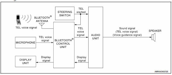
System Description
Refer to the owner's manual for Bluetooth telephone system operating instructions. NOTE: Cellular telephones must have their wireless connection set up (paired) before using the Bluetooth telephone system.
Bluetooth telephone system allows users who have a Bluetooth cellular telephone to make a wireless connection between their cellular telephone and the Bluetooth control unit. Hands-free cellular telephone calls can be sent and received. Some Bluetooth cellular telephones may not be recognized by the Bluetooth control unit. When a cellular telephone or the Bluetooth control unit is replaced, the telephone must be paired with the Bluetooth control unit. Different cellular telephones may have different pairing procedures. Refer to the cellular telephone operating manual.
BLUETOOTH CONTROL UNIT
When the ignition switch is turned to ACC or ON, the Bluetooth control unit will power up. During power up, the Bluetooth control unit is initialized and performs various self checks. Initialization may take up to 20 seconds.
If a phone is present in the vehicle and paired with the Bluetooth control unit, Nissan Voice Recognition will then become active. Bluetooth telephone functions can be turned off using the Nissan Voice Recognition system.
STEERING WHEEL AUDIO CONTROL SWITCHES
When buttons on the steering wheel audio control switch are pushed, the resistance in steering wheel audio control switch circuit changes depending on which button is pushed. The Bluetooth control unit uses this signal to perform various functions while navigating through the voice recognition system.
The following functions can be performed using the steering wheel audio control switch:
- Initiate self-diagnosis of the Bluetooth telephone system
- Start a voice recognition session
- Answer and end telephone calls
- Adjust the volume of calls
MICROPHONE
The microphone is located in the roof console assembly. The microphone sends a signal to the Bluetooth control unit. The microphone can be actively tested during self-diagnosis.
AUDIO UNIT
The audio unit receives signals from the Bluetooth control unit and sends audio signals to the speakers.
Component Parts Location
- Tweeter LH M143
- Display unit M109
- Tweeter RH M144
- Audio unit M133, M147
- Steering wheel audio control switches
- Front door speaker LH D3 RH D103
- Rear door speaker LH D209 RH D309
- Subwoofers (view of underside of parcel shelf) LH B16 RH B17
- Bluetooth control unit B125, B126, B130
- Subwoofer amp. B21
- Microphone R7
Component Description
| Part name | Description |
| Audio unit |
|
| Front door speaker | Receives telephone voice signals from the audio unit. |
| Tweeter | |
| Steering wheel audio control switches |
|
| Microphone | Sends voice signals to Bluetooth control unit.
Bluetooth control unit - Controls hands-free phone functions. - Receives display signals from audio unit. |
| Bluetooth control unit |
|
| Display unit |
|
| Bluetooth antenna | Sends telephone voice signal to Bluetooth control unit. |
 Audio system
SYSTEM DESCRIPTION
AUDIO SYSTEM
System Diagram
System Description
AUDIO SYSTEM
The audio system consists of the following components
Audio unit
Display unit
Bluetooth control unit
W ...
 Diagnosis system (audio unit)
Diagnosis Description
Self-diagnosis mode can perform the following items.
Versions display
Channel check diagnosis
Key check diagnosis
AV communication diagnosis
VERSIONS DISPLAY FUNCTI ...
Other materials:
Tilt motor
Description
The tilt motor is installed to the steering column assembly.
The tilt motor is activated with the automatic drive positioner control
unit.
The steering column is tilted upward/downward by changing the rotation
direction of tilt motor.
Component Function Check
1. CHECK F ...
Xenon headlamp
Description
OPERATION
Refer to EXL-10, "Component Description".
PRECAUTIONS FOR TROUBLE
DIAGNOSIS
Installation or removal of the connector must be done with the
lighting switch OFF.
When the lamp is illuminated (when the lighting switch is ON), do
not touch the harness, HID control ...
Door switch
Description
Detects door open/close condition.
Component Function Check
1.CHECK FUNCTION
With CONSULT
Check door switches DOOR SW-DR, DOOR SW-AS in Data Monitor mode with CONSULT.
Diagnosis Procedure
1.CHECK DOOR SWITCH INPUT SIGNAL
Turn ignition switch OFF.
Check signal between B ...
Nissan Maxima Owners Manual
- Illustrated table of contents
- Safety-Seats, seat belts and supplemental restraint system
- Instruments and controls
- Pre-driving checks and adjustments
- Monitor, climate, audio, phone and voice recognition systems
- Starting and driving
- In case of emergency
- Appearance and care
- Do-it-yourself
- Maintenance and schedules
- Technical and consumer information
Nissan Maxima Service and Repair Manual

0.005