Nissan Maxima Service and Repair Manual: U1263 USB
DTC Logic
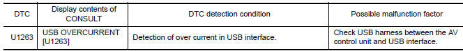
Diagnosis Procedure
1.CHECK USB HARNESS
Visually check USB harness.
 U1243 display unit
Description
Part name
Description
DISPLAY UNIT
Display image is controlled by the serial communication from AV
control unit.
Inputs the RGB i ...
 U1255 satellite radio tuner
Description
DTC Logic
Diagnosis Procedure
1.CHECK SATELLITE RADIO TUNER POWER SUPPLY AND GROUND CIRCUIT
Check satellite radio tuner power supply and ground circuit.
2.CHECK CONTINUITY COM ...
Other materials:
Combination switch system symptoms
SYMPTOM DIAGNOSIS
COMBINATION SWITCH SYSTEM SYMPTOMS
Symptom Table
Perform the data monitor of CONSULT to check for any malfunctioning
item.
Check the malfunction combinations
Identify the malfunctioning part from the agreed combination and repair
or replace the part.
...
Passenger compartment
Interior trunk access
Power moonroof (if so equipped)
Sun visors
Map lights
Rearview mirror. HomeLink Universal Transceiver
Glove box
Cup holders
Console box
Refer to the page number indicated in parentheses
for operating details. ...
U1300 AV comm circuit
Description
U1300 is indicated when a communication signal malfunction occurs. U1300 is
indicated along with DTCs that
identify components connected to the AV control unit through communication
lines. Determine the possible
malfunction cause from the table below.
SELF-DIAGNOSIS RESULTS DIS ...
Nissan Maxima Owners Manual
- Illustrated table of contents
- Safety-Seats, seat belts and supplemental restraint system
- Instruments and controls
- Pre-driving checks and adjustments
- Monitor, climate, audio, phone and voice recognition systems
- Starting and driving
- In case of emergency
- Appearance and care
- Do-it-yourself
- Maintenance and schedules
- Technical and consumer information
Nissan Maxima Service and Repair Manual

0.0087