Nissan Maxima Service and Repair Manual: Navigation system
System Diagram
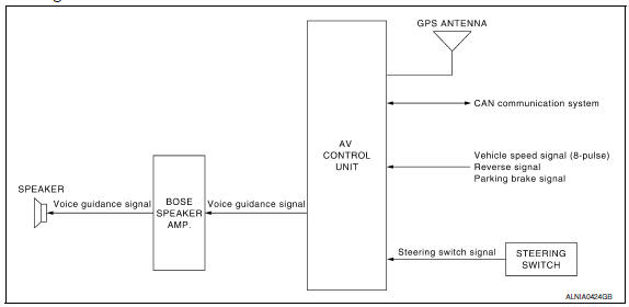
System Description
NOTE: Refer to NAVI System Owner's Manual for system operation. The navigation system periodically calculates the vehicle's current position according to the following three signals: Travel distance of the vehicle as determined by the vehicle speed sensor, turning angle of the vehicle as determined by the gyroscope (angular velocity sensor), and the direction of vehicle travel as determined by the GPS antenna (GPS information).
The current position of the vehicle is then identified by comparing the calculated vehicle position with map data read from the map data, which is stored in the hard disk drive (HDD) (map-matching), and indicated on the screen with a current-location mark.
By comparing the vehicle position detection results found by the GPS and by map-matching, more accurate vehicle position data can be used.
The current vehicle position will be calculated by detecting the distance the vehicle moved from the previous calculation point and its direction.
TRAVEL DISTANCE
Travel distance calculations are based on the vehicle speed input signal. Therefore, the calculation may become incorrect as the tires wear down. To prevent this, an automatic distance fine adjustment function has been adopted.
TRAVEL DIRECTION
Change in the travel direction of the vehicle is calculated by a gyroscope (angular velocity sensor) and a GPS antenna (GPS information). As the gyroscope and GPS antenna have both merit and demerit, input signals from them are prioritized in each situation. However, this order of priority may change in accordance with more detailed travel conditions so that the travel direction is detected more accurately
|
Type |
Advantage |
Disadvantage |
| Gyroscope (angular velocity sensor) |
|
|
| GPS antenna (GPS information) |
|
|
MAP-MATCHING
Map-matching is a function that repositions the vehicle on the road map when a new location is judged to be the most accurate. This is done by comparing the current vehicle position, calculated by the method described in the position detection principle, with the road map data around the vehicle, read from the map data stored on the HDD.
Therefore, the vehicle position may not be corrected after the vehicle is driven over a certain distance or time in which GPS information is hard to receive. In this case, the current-location mark on the display must be corrected manually.
CAUTION: The road map data is based on data stored on the HDD.
- In map-matching, alternative routes to reach the destination will
be
shown and prioritized, after the road on which the vehicle is currently
driven has been judged and the current-location mark has
been repositioned.
If there is an error in distance and/or direction, the alternative routes will be shown in different order of priority, and the wrong road can be avoided.
If two roads are running in parallel, they are of the same priority.
Therefore, the current-location mark may appear on either of them alternately, depending on maneuvering of the steering wheel and configuration of the road.
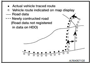
- Map-matching does not function correctly when the road on which
the vehicle is driving is new and not recorded on the HDD, or when
the road pattern stored in the map data and the actual road pattern
are different due to repair.
When driving on a road not present in the map, the map-matching function may find another road and position the current-location mark on it. Then, when the correct road is detected, the currentlocation mark may leap to it.
- Effective range for comparing the vehicle position and travel direction calculated by the distance and direction with the road data read from the HDD is limited. Therefore, when there is an excessive gap between the current vehicle position and the position on the map, correction by map-matching is not possible.
GPS (GLOBAL POSITIONING SYSTEM)
GPS (Global Positioning System) has been developed and controlled by the US Department of Defense. The system utilizes GPS satellite (NAVSTAR), sending out radio waves while flying on an orbit around the earth at the height of approx. 21,000 km (13,000 mi).
The GPS receiver calculates the vehicle's position in three dimensions (latitude/longitude/altitude) according to the time lag of the radio waves received from four or more GPS satellites (three-dimensional positioning). If radio waves were received only from three GPS satellites, the GPS receiver calculates the vehicle's position in two dimensions (latitude/longitude), utilizing the altitude data calculated previously by using radio waves from four or more GPS satellites (two-dimensional positioning).
Accuracy of the GPS will deteriorate under the following conditions.
- In two-dimensional positioning, the GPS accuracy will deteriorate when the altitude of the vehicle position changes.
- There may be an error of approximately 10 m (30 ft.) in position detected by three-dimensional positioning, which is more accurate than two-dimensional positioning. The accuracy can be even lower depending on the arrangement of the GPS satellites utilized for the positioning.
- Position detection is not possible when the vehicle is in an area where radio waves from the GPS satellite do not reach, such as in a tunnel, parking lot in a building, and under an elevated highway. Radio waves from the GPS satellites may not be received when some object is located over the GPS antenna.
- Position correction by GPS is not available while the vehicle is stopped.
Component Parts Location
- Tweeter LH M51
- Center speaker M130
- Tweeter RH M52
- AV control unit M160, M161, M162, M163, M164, M165, M166, M167, M168 (located behind A/C and AV switch assembly)
- Display unit M142, M151
- A/C and AV switch assembly M98
- Steering angle sensor M53 [located in steering column behind combination switch (spiral cable)]
- Steering wheel audio control switches
- USB interface M211(view in center console)
- Aux in jack M209
- Microphone R7
- Rear view camera T101
- Front door speaker
LH D3
RH D103 - Rear door speaker
LH D202
RH D302 - Rear subwoofers (view under rear
parcel shelf)
LH B106
RH B107 - BOSE speaker amp B109, B110
Component Description
|
Part name |
Description |
| AV control unit |
|
| BOSE speaker amp | Voice guidance signal is input from AV control unit, and it is output to speakers. |
| Tweeter | Voice guidance signal from BOSE speaker amp. is output |
| Steering wheel audio control switches |
|
| Microphone | Sends voice signals to AV control unit |
| GPS antenna | GPS signal is received and is output to AV control unit. |
 Audio system
System Diagram
System Description
AUDIO SYSTEM
The audio system consists of the following components
AV control unit
Display unit
BOSE speaker amp.
Window antenna
Steering wheel aud ...
 Rear view monitor system
System Diagram
System Description
When the shift selector is in the R position, the display unit shows a view
to the rear of the vehicle. Lines which
indicate the vehicle clearance and dista ...
Other materials:
Intake Manifold
Removal and Installation
Intake manifold
Intake manifold gaskets
Refer to INSTALLATION
REMOVAL
WARNING: To avoid the danger of being
scalded, do not drain the coolant when the engine is hot.
Release the fuel pressure. Refer to EC-592, "Inspection".
Disconnect the ba ...
Anti-lock Braking System (ABS)
WARNING
The ABS is a sophisticated device, but it
cannot prevent accidents resulting from
careless or dangerous driving techniques.
It can help maintain vehicle control
during braking on slippery surfaces.
Remember that stopping distances on
slippery surfaces will be longer than on
norma ...
Operating tips
When the engine coolant temperature and
outside air temperature are low, the air flow
from the foot outlets may not operate for a
maximum of 150 seconds. However, this is
not a malfunction. After the coolant temperature
warms up, air flow from the foot outlets
will operate normally.
...
Nissan Maxima Owners Manual
- Illustrated table of contents
- Safety-Seats, seat belts and supplemental restraint system
- Instruments and controls
- Pre-driving checks and adjustments
- Monitor, climate, audio, phone and voice recognition systems
- Starting and driving
- In case of emergency
- Appearance and care
- Do-it-yourself
- Maintenance and schedules
- Technical and consumer information
Nissan Maxima Service and Repair Manual

0.0066