Nissan Maxima Service and Repair Manual: Audio system
System Diagram
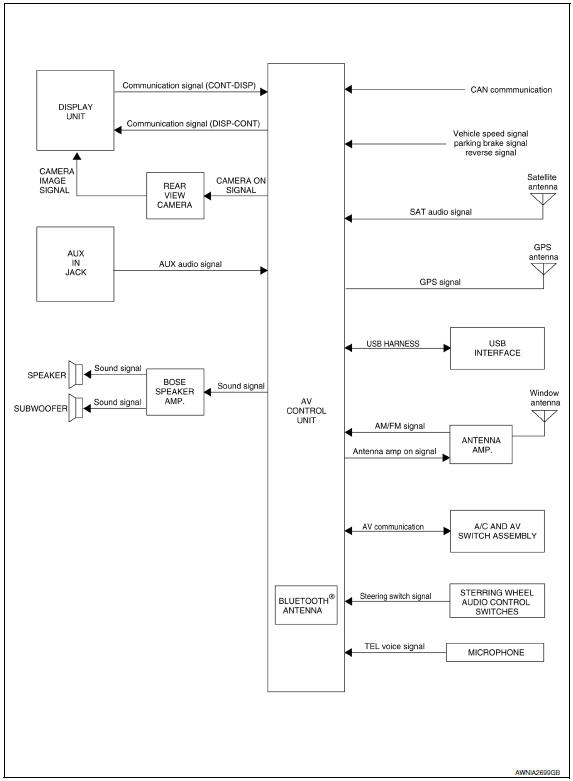
System Description
AUDIO SYSTEM
The audio system consists of the following components
- AV control unit
- Display unit
- BOSE speaker amp.
- Window antenna
- Steering wheel audio control switches
- A/C and AV switch assembly
- Front door speakers
- Tweeters
- Center speaker
- Rear door speakers
- Rear subwoofers
When the audio system is on, radio signals are received by the window antenna. The AV control unit then sends audio signals to the BOSE speaker amp. The BOSE speaker amp. amplifies the audio signals before sending them to the front door speakers, tweeters, center speaker, rear door speakers and the rear subwoofers.
Refer to Owner's Manual for audio system operating instructions.
SATELLITE RADIO SYSTEM (IF EQUIPPED)
The satellite radio system consists of the following components
- Satellite antenna
- AV control unit
When the satellite radio system is on, radio signals are supplied to the AV control unit from the satellite antenna. The AV control unit then sends audio signals to the BOSE speaker amp.
Refer to Owner's Manual for satellite radio system operating instructions.
SPEED SENSITIVE VOLUME SYSTEM
Volume level of this system goes up and down automatically in proportion to the vehicle speed. The control level can be selected by the customer. Refer to Owner's Manual for operating instructions.
Component Parts Location
- Tweeter LH M51
- Center speaker M130
- Tweeter RH M52
- AV control unit M160, M161, M162, M163, M164, M165, M166, M167, M168 (located behind A/C and AV switch assembly)
- Display unit M142, M51
- A/C and AV switch assembly M98
- Steering angle sensor M53 [located in steering column behind combination switch (spiral cable)]
- Steering wheel audio control switches
- USB interface M211(view in center console)
- Aux in jack M209
- Microphone R7
- Rear view camera T101
- Front door speaker
LH D3
RH D103 - Rear door speaker
LH D202
RH D302 - Rear subwoofers (view under rear
parcel shelf)
LH B106
RH B107 - BOSE speaker amp B109, B110
Component Description
|
Part name |
Description |
| AV control unit | Controls audio system, USB connection, AUX IN connection, NAVI functions and satellite radio system functions |
| Display unit | Displays all audio and climate control related information |
| BOSE speaker amp | Receives power (amp ON) and audio signals from AV control unit and outputs audio signals to each speaker |
| Steering wheel audio control switches |
|
| Front door speakers |
|
| Tweeters |
|
| Center speaker |
|
| Rear door speakers |
|
| Rear subwoofers |
|
| Satellite antenna (if so equipped) | Audio signal (satellite radio) is received and output to AV control unit. |

 Navigation system
System Diagram
System Description
NOTE:
Refer to NAVI System Owner's Manual for system operation.
The navigation system periodically calculates the vehicle's current position
accor ...
Other materials:
General maintenance
During the normal day-to-day operation of the
vehicle, general maintenance should be performed
regularly as prescribed in this section. If
you detect any unusual sounds, vibrations or
smells, be sure to check for the cause or have a
NISSAN dealer do it promptly. In addition, it is
recommended ...
Bose speaker amp
Removal and Installation
Bose speaker amp.
Bose speaker amp. screws
REMOVAL
NOTE: If removing the BOSE speaker amp.
bracket, it is necessary to remove the parcel shelf finisher. The BOSE
speaker amp. can be removed without removing the BOSE speaker amp. bracket.
Disconnect the ...
Vacuum lines
Inspection
VISUAL INSPECTION
Check for improper assembly, damage and deterioration. Replace as necessary.
CHECK VALVE INSPECTION
Airtightness Inspection
Use a suitable tool to check the built-in check valve. Replace the
vacuum hose with the built-in check valve as an assembly if the vacuu ...
Nissan Maxima Owners Manual
- Illustrated table of contents
- Safety-Seats, seat belts and supplemental restraint system
- Instruments and controls
- Pre-driving checks and adjustments
- Monitor, climate, audio, phone and voice recognition systems
- Starting and driving
- In case of emergency
- Appearance and care
- Do-it-yourself
- Maintenance and schedules
- Technical and consumer information
Nissan Maxima Service and Repair Manual

0.0078