Nissan Maxima Service and Repair Manual: Diagnosis system (bluetooth control unit)
Diagnosis Description
The Bluetooth control unit has two diagnostic checks. The first diagnostic check is performed automatically every ignition cycle during control unit initialization. The second diagnostic check is performed by the technician using the steering wheel audio control switches prior to trouble diagnosis.
BLUETOOTH CONTROL UNIT INITIALIZATION CHECKS
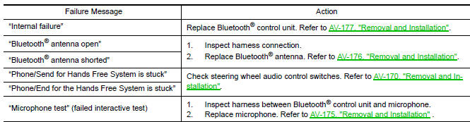
- Internal control unit failure
- Bluetooth antenna connection open or shorted
- Steering wheel audio control switches [
 (PHONE/SEND),
  (PHONE/END)]
stuck closed
(PHONE/END)]
stuck closed - Vehicle speed pulse count
- Microphone connection test (with playback to operator)
- Bluetooth inquiry check
OPERATION PROCEDURE
- Turn ignition switch to ACC or ON.
- Wait for the Bluetooth system to complete initialization. This may take up to 20 seconds.
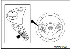
- Press and hold the steering wheel audio control switch
 (PHONE/SEND) button for at least 5
seconds. The Bluetooth system will begin to play a verbal prompt.
(PHONE/SEND) button for at least 5
seconds. The Bluetooth system will begin to play a verbal prompt.
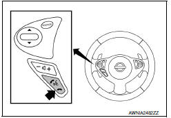
- While the prompt is playing, press and hold the steering wheel audio
control switch
 (PHONE/END) button until you
hear the "Diagnostics mode" prompt. The Bluetooth system will sound a
5-second beep.
(PHONE/END) button until you
hear the "Diagnostics mode" prompt. The Bluetooth system will sound a
5-second beep. - While the beep is sounding, press and hold the steering wheel audio
control switch
 (PHONE/END) button again until
you hear prompts.
(PHONE/END) button again until
you hear prompts. - The Bluetooth system has now entered into the diagnostic mode. Results of the diagnostic checks will be verbalized to the technician. Refer to AV-101, "Work Flow".
- After the failure records are reported, an interactive microphone test will be performed. Follow the voice prompt. If the microphone test fails, refer to AV-101, "Work Flow".
Work Flow
 Diagnosis system (audio unit)
Diagnosis Description
Self-diagnosis mode can perform the following items.
Versions display
Channel check diagnosis
Key check diagnosis
AV communication diagnosis
VERSIONS DISPLAY FUNCTI ...

Other materials:
Performance test
Inspection
INSPECTION PROCEDURE
Connect recovery/recycling/recharging equipment (for HFC-134a) or
manifold gauge.
Start the engine, and set to the following condition.
Maintain test condition until A/C system becomes stable. (Approximately
10 minutes)
Check that test results ...
The fuel gauge pointer does not move
Description
Fuel gauge needle will not move from a certain position.
Diagnosis Procedure
1.CHECK COMBINATION METER INPUT SIGNAL
Select "METER/M&A" on CONSULT.
Using "FUEL METER" of "DATA MONITOR", compare
the monitor value with the fuel gauge reading on
the co ...
Power supply and ground circuit
BCM
BCM : Diagnosis Proce
1. CHECK FUSE AND FUSIBLE LINK
Check if the following BCM fuses or fusible link are blow
2. CHECK POWER SUPPLY CIRCUIT
Turn ignition switch OFF.
Disconnect BCM.
Check voltage between BCM harness connector and ground.
3. CHECK GROUND CIRCUIT
Check con ...
Nissan Maxima Owners Manual
- Illustrated table of contents
- Safety-Seats, seat belts and supplemental restraint system
- Instruments and controls
- Pre-driving checks and adjustments
- Monitor, climate, audio, phone and voice recognition systems
- Starting and driving
- In case of emergency
- Appearance and care
- Do-it-yourself
- Maintenance and schedules
- Technical and consumer information
Nissan Maxima Service and Repair Manual

0.0054