Nissan Maxima Service and Repair Manual: U1000 CAN comm circuit
Description
CAN (Controller Area Network) is a serial communication line for real time application. It is an on-vehicle multiplex communication line with high data communication speed and excellent error detection ability. Many electronic control units are equipped onto a vehicle and each control unit shares information and links with other control units during operation (not independent). In CAN communication, control units are connected with 2 communication lines (CAN-H, CAN-L) allowing a high rate of information transmission with less wiring. Each control unit transmits/receives data but selectively reads required data only.
DTC Logic
DTC DETECTION LOGIC
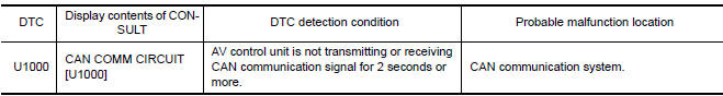
Diagnosis Procedure
1.PERFORM SELF DIAGNOSTIC
- Turn ignition switch ON and wait for 2 seconds or more.
- Check "Self Diagnostic Result" of "AV Control Unit".

 U1010 control unit (CAN)
DTC Logic
DTC DETECTION LOGIC
U1200 AV CONTROL UNIT
DTC Logic
U1201 AV CONTROL UNIT
DTC Logic
U1202 AV CONTROL UNIT
DTC Logic
...
Other materials:
Front tweeter
Removal and Installation
REMOVAL
Remove the front pillar finisher. Refer to IP-10, "Exploded View".
Remove the front tweeter speaker grille. Refer to IP-10, "Exploded
View".
Remove the front tweeter speaker screws (A).
Pull out front tweeter speaker (1), disconnect the harness
con ...
Starting the vehicle
1. After starting the engine, fully depress the
foot brake pedal before moving the shift
lever out of the P (Park) position.
2. Keep the foot brake pedal depressed and
move the shift lever into a driving gear.
3. Release the parking brake and the foot brake
pedal, then gradually start the ...
v DLC and HVAC circuit
Diagnosis Procedure
1.CHECK HARNESS CONTINUITY (OPEN CIRCUIT)
Turn the ignition switch OFF.
Disconnect the battery cable from the negative terminal.
Disconnect the following harness connectors.
ECM
A/C auto amp.
Check the continuity between the data link connector and the A/C ...
Nissan Maxima Owners Manual
- Illustrated table of contents
- Safety-Seats, seat belts and supplemental restraint system
- Instruments and controls
- Pre-driving checks and adjustments
- Monitor, climate, audio, phone and voice recognition systems
- Starting and driving
- In case of emergency
- Appearance and care
- Do-it-yourself
- Maintenance and schedules
- Technical and consumer information
Nissan Maxima Service and Repair Manual

0.0056