Nissan Maxima Service and Repair Manual: U1010 control unit (CAN)
Nissan Maxima Service and Repair Manual / Driver information & multimedia / Audio, visual & navigation system / DTC/circuit diagnosis / U1010 control unit (CAN)
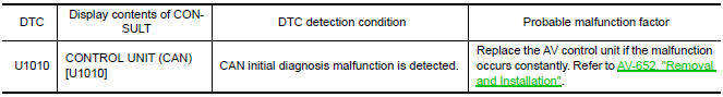
DTC Logic
DTC DETECTION LOGIC
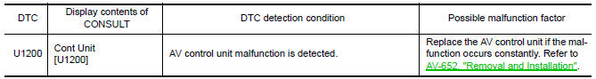
U1200 AV CONTROL UNIT
DTC Logic
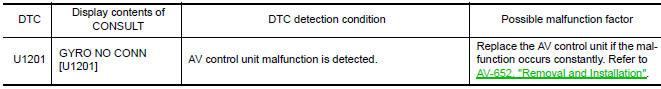
U1201 AV CONTROL UNIT
DTC Logic
U1202 AV CONTROL UNIT
DTC Logic

 U1000 CAN comm circuit
Description
CAN (Controller Area Network) is a serial communication line for real time
application. It is an on-vehicle multiplex
communication line with high data communication speed and excelle ...
 U1204 AV control unit
DTC Logic
Diagnosis Procedure
1.PERFORM THE SELF-DIAGNOSIS
Delete the "self-diagnosis" results of "MULTI AV". Turn ignition
switch OFF.
Turn ignition switch ON. Perform the self-diagnos ...
Other materials:
Wiring diagram
CHARGING SYSTEM
Wiring Diagram
...
Brake tube and hose
Hydraulic Circuit
Actuator
Master cylinder
Brake booster
Connector A. Union bolt
18.2 N*m (1.9 kg-m, 13 ft-lb)
B. Flare nut M12
22.1 N*m (2.3 kg-m, 16 ft-lb)
C. Flare nut M10
16.2 N*m (1.7 kg-m, 12 ft-lb)
CAUTION:
All hoses and piping (tubes) must be free from e ...
Wiring diagram
MONOCHROME DISPLAY
Wiring Diagram - Without BOSE Audio system
...
Nissan Maxima Owners Manual
- Illustrated table of contents
- Safety-Seats, seat belts and supplemental restraint system
- Instruments and controls
- Pre-driving checks and adjustments
- Monitor, climate, audio, phone and voice recognition systems
- Starting and driving
- In case of emergency
- Appearance and care
- Do-it-yourself
- Maintenance and schedules
- Technical and consumer information
Nissan Maxima Service and Repair Manual

© 2017-2026 Copyright www.nimainfo.com
0.0056
0.0056