Nissan Maxima Service and Repair Manual: Tilt motor
Exploded View
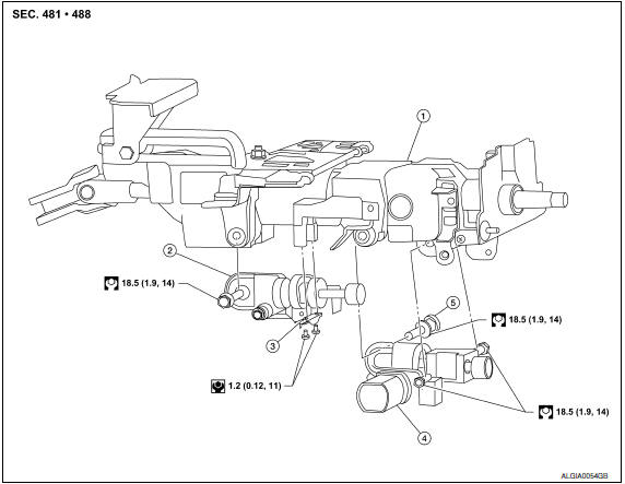
- Steering column assembly
- Telescope motor
- Telescope motor link bracket
- Tilt motor
- Tilt motor bolt cap
Removal and Installation
REMOVAL
- Remove instrument lower panel LH. Refer to IP-19, "Removal and Installation".
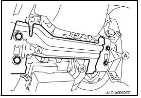
- Remove lower knee protector (LH) bolts (A) and the lower knee protector (LH) (B).
- Telescope the steering wheel to the full out position and tilt to highest position. NOTE: If either function is inoperative you can do this manually prior to installation.
- Remove the steering column covers. Refer to IP-11, "Removal and
Installation".
NOTE: The tilt/telescope switch can remain attached to the side cover.
- Remove the tilt motor as follows.
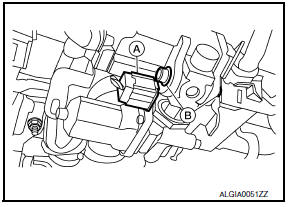
- Disconnect the harness connector (A) from the tilt motor.
- Remove the tilt motor link bolts (B).
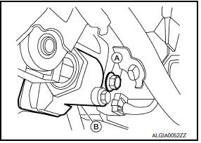
- Remove the tilt motor bolt (A) from the RH side of column.
- Remove the tilt motor (B).
NOTE: If the steering wheel could not be tilted to the highest position, manually tilt steering wheel to the highest position.
INSTALLATION
Installation is in the reverse order of removal.
NOTE:
- When installing the tilt motor link bolts, manually move steering wheel up and down to align the bolt holes.
- Inform customer that they will need to reset their Automatic Drive Positioner (ADP) settings.
 Steering wheel
Removal and Installation
REMOVAL
NOTE: When removing spiral cable, use tape
so that the case and rotating part keep aligned. This will prevent neutral
position alignment procedure during spiral ...
 Telescopic motor
Exploded View
Steering column assembly
Telescope motor
Telescope motor link bracket
Tilt motor
Tilt motor bolt cap
Removal and Installation
REMOVAL
Remove instrument lower pan ...
Other materials:
Power supply and ground circuit
BCM
BCM : Diagnosis Procedure
1. CHECK FUSE AND FUSIBLE LINK
Check if the following BCM fuses or fusible link are blown.
2. CHECK POWER SUPPLY CIRCUIT
Turn ignition switch OFF.
Disconnect BCM.
Check voltage between BCM harness connector and ground.
3. CHECK GROUND CIRCUIT
Che ...
Unit disassembly and assembly
COOLING FAN
Disassembly and Assembly of Cooling Fan
Fan blade
Fan shroud
Fan motor
DISASSEMBLY
Remove fan blade nut.
Remove fan blade from fan motor.
Remove fan motor bolts and remove fan motor from fan shroud.
ASSEMBLY
Assembly is in the reverse order of disassembly. ...
Power supply and ground circuit
AUDIO UNIT
AUDIO UNIT : Diagnosis Procedure
1.CHECK FUSES
2.POWER SUPPLY CIRCUIT CHECK
Disconnect audio unit connector M132.
Check voltage between the audio unit connector M132 and ground.
3.GROUND CIRCUIT CHECK
Inspect audio unit case ground.
DISPLAY UNIT
DISPLAY UNIT : Dia ...
Nissan Maxima Owners Manual
- Illustrated table of contents
- Safety-Seats, seat belts and supplemental restraint system
- Instruments and controls
- Pre-driving checks and adjustments
- Monitor, climate, audio, phone and voice recognition systems
- Starting and driving
- In case of emergency
- Appearance and care
- Do-it-yourself
- Maintenance and schedules
- Technical and consumer information
Nissan Maxima Service and Repair Manual

0.0057