Nissan Maxima Service and Repair Manual: P0705 transmission range switch A
Description
- The Transmission range switch is included in the control valve assembly.
- The Transmission range switch includes 4 transmission position switches.
- TCM judges the selector lever position by the Transmission range switch signal.

DTC Logic
DTC DETECTION LOGIC

DTC CONFIRMATION PROCEDURE
CAUTION: Always drive vehicle at a safe speed.
NOTE: Immediately after performing any "DTC CONFIRMATION PROCEDURE", always turn ignition switch OFF.
Then wait at least 10 seconds before performing the next test.
1.CHECK DTC DETECTION
 With CONSULT
- Turn ignition switch ON.
- Select "Data Monitor" in "TRANSMISSION".
- Start engine.
- Drive vehicle and maintain the following conditions for at least 2 consecutive seconds.
 With GST
Follow the procedure "With CONSULT".
Diagnosis Procedure
Regarding Wiring Diagram information, refer to TM-126, "Wiring Diagram".
1.CHECK CVT POSITION
- Disconnect CVT unit connector.
- Remove control cable from manual lever. Refer toTM-173, "Exploded View".
- Check transmission range switch. Refer to TM-51, "Component Inspection (Transmisson Range Switch)".
2. CHECK HARNESS BETWEEN TCM AND TRANSMISSION RANGE SWITCH (PART 1)
- Turn ignition switch OFF.
- Disconnect TCM connector.
- Check continuity between TCM vehicle side harness connector terminals and CVT unit vehicle side harness connector terminals.
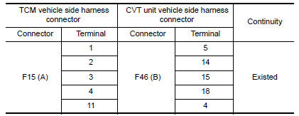
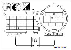
3. CHECK HARNESS BETWEEN TCM AND TRANSMISSION RANGE SWITCH (PART 2)
Check continuity between TCM vehicle side harness connector terminals and ground.
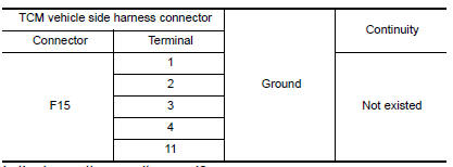
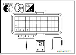
4.DETECT MALFUNCTIONING ITEMS
Check TCM connector pin terminals for damage or loose connection with harness connector.
Component Inspection (Transmisson Range Switch)
1.CHECK TRANSMISSION RANGE SWITCH
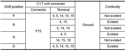
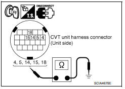
Check the continuity of the transmission range switch by changing selector lever to various positions and checking continuity between CVT unit terminals and ground.
 P0703 brake switch B
Description
BCM detects ON/OFF state of the stop lamp switch and transmits the data to
the TCM via CAN communication
by converting the data to a signal.
DTC Logic
DTC DETECTION LOGIC
DTC CON ...
 P0710 transmission fluid temperature sensor A
Description
The CVT fluid temperature sensor detects the CVT fluid temperature and sends
a signal to the TCM.
DTC Logic
DTC DETECTION LOGIC
DTC CONFIRMATION PROCEDURE
CAUTION: Always drive ve ...
Other materials:
Steering wheel
WARNING
Do not adjust the steering wheel while
driving. You could lose control of your
vehicle and cause an accident.
Do not adjust the steering wheel any
closer to you than is necessary for
proper steering operation and comfort.
The driver's air bag inflates with great
force. If ...
Driver air bag module
Exploded View
Driver air bag module
Side lid
Driver air bag module harness connectors
Steering wheel switch assembly connector
Driver air bag module bolt
Removal and Installation
CAUTION:
Before servicing, turn ignition switch OFF, disconnect both
battery terminals and wai ...
Rear combination lamp
Disassembly and Assembly
Rear combination lamp
Rear side marker lamp socket
Rear side marker lamp bulb
Rear turn signal lamp socket
Rear turn signal lamp bulb
Back-up lamp socket
Back-up lamp bulb
DISASSEMBLY
Rotate the rear side marker lamp socket counterclockwise and ...
Nissan Maxima Owners Manual
- Illustrated table of contents
- Safety-Seats, seat belts and supplemental restraint system
- Instruments and controls
- Pre-driving checks and adjustments
- Monitor, climate, audio, phone and voice recognition systems
- Starting and driving
- In case of emergency
- Appearance and care
- Do-it-yourself
- Maintenance and schedules
- Technical and consumer information
Nissan Maxima Service and Repair Manual
0.0063
