Nissan Maxima Service and Repair Manual: P0643 sensor power supply
DTC Logic
DTC DETECTION LOGIC
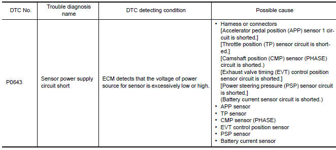
DTC CONFIRMATION PROCEDURE
1.PRECONDITIONING
If DTC Confirmation Procedure has been previously conducted, always perform the following before conducting the next test.
- Turn ignition switch OFF and wait at least 10 seconds.
- Turn ignition switch ON.
- Turn ignition switch OFF and wait at least 10 seconds.
TESTING CONDITION: Before performing the following procedure, confirm that battery voltage is more than 8 V at idle
2.PERFORM DTC CONFIRMATION PROCEDURE
- Turn ignition switch ON.
- Start engine and let it idle for 1 second.
- Check DTC
Diagnosis Procedure
1.CHECK GROUND CONNECTION
- Turn ignition switch OFF.
- Check ground connection E9.
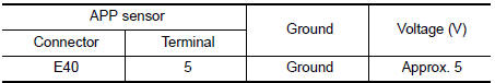
2.CHECK ACCELERATOR PEDAL POSITION SENSOR 1 POWER SUPPLY CIRCUIT
- Disconnect accelerator pedal position (APP) sensor harness connector.
- Turn ignition switch ON.
- Check the voltage between APP sensor harness connector and ground.
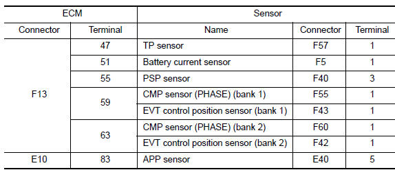
3.CHECK SENSOR POWER SUPPLY CIRCUIT
Check harness for short to power and short to ground, between the following terminals.
4.CHECK COMPONENTS
Check the following.
- Camshaft position sensor (PHASE) (Refer to EC-302, "Component Inspection".)
- EVT control position sensor (Refer to EC-402, "Component Inspection".)
- Battery current sensor (Refer to EC-415, "Component Inspection".)
- Power steering pressure sensor
5.CHECK TP SENSOR
6.REPLACE ELECTRIC THROTTLE CONTROL ACTUATOR
- Replace electric throttle control actuator.
7.CHECK APP SENSOR
8.REPLACE ACCELERATOR PEDAL ASSEMBLY
- Replace accelerator pedal assembly.
9.CHECK INTERMITTENT INCIDENT
 P0607 ECM
Description
CAN (Controller Area Network) is a serial communication line for real time
application. It is an on-vehicle multiplex
communication line with high data communication speed and excelle ...
 P0850 PNP switch
Description
When the selector lever position is P or N, park/neutral position (PNP)
signal from the TCM is sent to ECM.
DTC Logic
DTC DETECTION LOGIC
DTC CONFIRMATION PROCEDURE
1.INSPECTION ...
Other materials:
System maintenance
The sensor A is located behind the lower grille
of the front bumper.
To keep the system operating properly, be sure to
observe the following:
Always keep the sensor area of the front
bumper clean.
Do not strike or damage the areas around
the sensor.
Do not cover or attach st ...
Aux image signal circuit
Description
Transmits the image signal of AUX device from auxiliary input jacks to
AV control unit.
AV control unit transmits the image signal that is input to the
display unit.
Diagnosis Procedure
1.CHECK CONTINUITY AUX IMAGE SIGNAL CIRCUIT
Turn ignition switch OFF.
Disconnect ...
Front wiper and washer switch
Removal and Installation
NOTE:The front wiper and washer switch is
part of the combination switch assembly.
REMOVAL
Disconnect battery.
CAUTION:
Before servicing, disconnect both battery terminals and wait
at least three minutes.
Do not use air tools or electric tools for servici ...
Nissan Maxima Owners Manual
- Illustrated table of contents
- Safety-Seats, seat belts and supplemental restraint system
- Instruments and controls
- Pre-driving checks and adjustments
- Monitor, climate, audio, phone and voice recognition systems
- Starting and driving
- In case of emergency
- Appearance and care
- Do-it-yourself
- Maintenance and schedules
- Technical and consumer information
Nissan Maxima Service and Repair Manual

0.0064