Nissan Maxima Service and Repair Manual: Normal operating condition
Description
The majority of the audio concerns are the result of outside causes (bad CD, electromagnetic interference, etc.).
NOISE
The following noise results from variations in field strength, such as fading noise and multi-path noise, or external noise from trains and other sources. It is not a malfunction.
- Fading noise: This noise occurs because of variations in the field strength in a narrow range due to mountains or buildings blocking the signal.
- Multi-path noise: This noise results from the waves sent directly from the broadcast station arriving at the antenna at a different time from the waves which reflect off mountains or buildings.
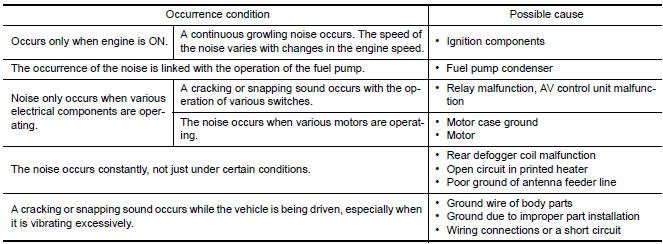
The vehicle itself can be a source of noise if noise prevention parts or electrical equipment is malfunctioning.
Check if noise is caused and/or changed by engine speed, ignition switch turned to each position, and operation of each piece of electrical equipment, and determine the cause.
NOTE: The source of the noise can be found easily by listening to the noise while removing the fuses of electrical components, one by one.
Type of Noise and Possible Cause
RELATED TO HANDS-FREE PHONE
| Symptom | Cause and Counter measure |
| Does not recognize cellular phone connection (No connection is displayed on the display at the guide). | Some Bluetooth enabled cellular phones may not be recognized by
the in-vehicle phone module.
Refer to "RELATED TO HANDS-FREE PHONE (Check Compatibility)" in AV-304, "Symptom Table". |
| Cannot use hands-free phone. |
Customer will not be able to use a hands-free phone under the following conditions:
NOTE: While a cellular phone is connected through the Bluetooth wireless connection, the battery power of the cellular phone may discharge quicker than usual. The Bluetooth Hands-Free Phone System cannot charge cellular phones. |
| The other party's voice cannot be heard by hands-free phone. | When the radio wave condition is not ideal or ambient sound is too loud, it may be difficult to hear the other person's voice during a call. |
| Poor sound quality. | Do not place the cellular phone in an area surrounded by metal or far away from the in-vehicle phone module to prevent tone quality degradation and wireless connection disruption. |
 Audio system
Symptom Table
AUDIO SYSTEM
Symptoms
Check items
Probable malfunction location
The disk cannot be removed
AV control unit
Malfunction in AV control unit.
Refer to AV-311, ...
 Precaution
PRECAUTIONS
Precaution for Supplemental Restraint System (SRS) "AIR BAG" and
"SEAT BELT PRE-TENSIONER"
The Supplemental Restraint System such as "AIR BAG" and "SEAT BELT
PRE-TENSIONER", used alo ...
Other materials:
RearView Monitor (if so equipped)
1. CAMERA button
WARNING
Failure to follow the warnings and instructions
for proper use of the Rear-
View Monitor system could result in serious
injury or death.
RearView Monitor is a convenience feature
and is not a substitute for proper
backing. Always turn and look out the
...
Daytime running light system
Wiring Diagram
...
Precaution
PRECAUTIONS
Precaution for Supplemental Restraint System (SRS) "AIR BAG" and
"SEAT BELT PRE-TENSIONER"
The Supplemental Restraint System such as "AIR BAG" and "SEAT BELT
PRE-TENSIONER", used along with a front seat belt, helps to reduce the risk
or severity of injury to the driver and front ...
Nissan Maxima Owners Manual
- Illustrated table of contents
- Safety-Seats, seat belts and supplemental restraint system
- Instruments and controls
- Pre-driving checks and adjustments
- Monitor, climate, audio, phone and voice recognition systems
- Starting and driving
- In case of emergency
- Appearance and care
- Do-it-yourself
- Maintenance and schedules
- Technical and consumer information
Nissan Maxima Service and Repair Manual

0.0063