Nissan Maxima Service and Repair Manual: Headlamp (LO) circuit
Description
The IPDM E/R (intelligent power distribution module engine room) controls the headlamp low relay based on inputs from the BCM over the CAN communication lines. When the headlamp low relay is energized, power flows through fuses 51 and 52, located in the IPDM E/R. Power then flows to the front combination lamps to the headlamp low beam.
Component Function Check
1.CHECK HEADLAMP (LO) OPERATION
WITHOUT CONSULT
- Start IPDM E/R auto active test. Refer to PCS-11, "Diagnosis Description".
- Check that the headlamp is turned ON.
NOTE: HI/LO is repeated 1 second each when using the IPDM E/R auto active test.
CONSULT
- Select "EXTERNAL LAMPS" of IPDM E/R active test item.
- While operating the test item, check that the headlamp is turned ON.
LO : Headlamp ON
OFF : Headlamp OFF
Diagnosis Procedure
1.CHECK HEADLAMP (LO) FUSES
- Turn the ignition switch OFF.
- Check that the following fuses are not open

2.CHECK HEADLAMP (LO) OUTPUT VOLTAGE
CONSULT
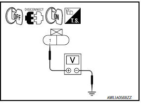
- Turn the ignition switch OFF.
- Disconnect the front combination lamp connector.
- Turn the ignition switch ON.
- Select "EXTERNAL LAMPS" of IPDM E/R active test item.
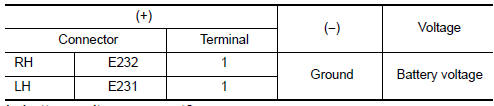
- With EXTERNAL LAMPS ON, check the voltage between the combination lamp connector and ground.
3.CHECK HEADLAMP (LO) CIRCUIT FOR OPEN
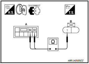
- Turn the ignition switch OFF.
- Disconnect IPDM E/R connector E200.
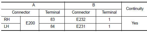
- Check continuity between the IPDM E/R harness connector (A) and the front combination lamp harness connector (B).
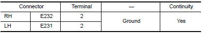
4.CHECK FRONT COMBINATION LAMP (LO) GROUND CIRCUIT
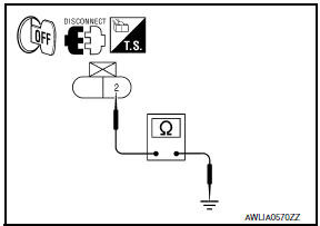
Check continuity between the front combination lamp harness connector terminal and ground.
 Headlamp (HI) circuit
Description
The IPDM E/R (intelligent power distribution module engine room) controls the
headlamp high relay based on inputs from the BCM over the CAN communication
lines. When the headlamp high ...
 Xenon headlamp
Description
OPERATION
Refer to EXL-10, "Component Description".
PRECAUTIONS FOR TROUBLE
DIAGNOSIS
Installation or removal of the connector must be done with the
lighting switch OFF.
When ...
Other materials:
P0420, P0430 three way catalyst function
DTC Logic
DTC DETECTION LOGIC
The ECM monitors the switching frequency ratio of air fuel ratio (A/F)
sensor 1 and heated oxygen sensor 2.
A three way catalyst (manifold) with high oxygen storage capacity
will indicate a low switching frequency of heated oxygen sensor 2.
As oxygen sto ...
P1740 select solenoid
Description
The lock-up select solenoid valve controls
lock-up clutch pressure or forward clutch pressure (reverse brake
pressure).
When controlling lock-up clutch, the valve is
turned OFF. When controlling forward clutch, it is turned ON.
DTC Logic
DTC DET ...
Water outlet and water piping
Removal and Installation
Heater hose
Clamp
Water hose
Clamp
Water outlet
Gasket
Gasket
Water connector
O-ring
Water bypass pipe
Clamp
Water hose
Heater pipe
Water hose
Heater hose
Engine coolant temperature sensor
Clamp
Radiator hose (upper)
&n ...
Nissan Maxima Owners Manual
- Illustrated table of contents
- Safety-Seats, seat belts and supplemental restraint system
- Instruments and controls
- Pre-driving checks and adjustments
- Monitor, climate, audio, phone and voice recognition systems
- Starting and driving
- In case of emergency
- Appearance and care
- Do-it-yourself
- Maintenance and schedules
- Technical and consumer information
Nissan Maxima Service and Repair Manual

0.0071