Nissan Maxima Service and Repair Manual: B2578, B2579 in-vehicle sensor
Description
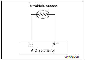
In-vehicle Sensor
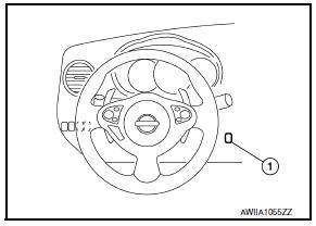
- The in-vehicle sensor (1) is located on instrument lower cover (LH).
- It converts variations in compartment air temperature drawn from the aspirator into a resistance value. It is then input into the A/C auto amp.
In-vehicle Sensor Circuit
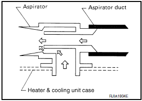
Aspirator
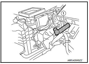
The aspirator (1) is located on driver side of heater & cooling unit assembly. It produces vacuum pressure due to air discharged from the heater & cooling unit assembly, continuously taking compartment air in the aspirator.
DTC Logic
DTC DETECTION LOGIC
NOTE: If DTC is displayed along with DTC U1000 or U1010, first diagnose the DTC U1000 or U1010.
DTC CONFIRMATION PROCEDURE
1.CHECK WITH SELF-DIAGNOSIS FUNCTION OF CONSULT
- Using CONSULT, perform "SELF-DIAGNOSIS RESULTS" of HVAC.
- Check if any DTC No. is displayed in the self-diagnosis results.
NOTE: If DTC is displayed along with DTC U1000 or U1010, first diagnose the DTC U1000 or U1010.
Diagnosis Procedure
1.CHECK IN-VEHICLE SENSOR POWER SUPPLY
- Disconnect in-vehicle sensor connector.
- Turn ignition switch ON.
3. Check voltage between in-vehicle sensor harness connector M34 terminal 1 and ground.
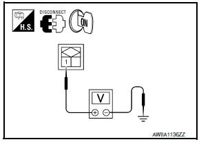
1 - Ground: Approx. 5V
2.CHECK CONTINUITY BETWEEN IN-VEHICLE SENSOR AND A/C AUTO AMP.
- Turn ignition switch OFF.
- Disconnect A/C auto amp. connector.
- Check continuity between in-vehicle sensor harness connector M34 (A) terminal 2 and A/C auto amp. harness connector M37 (B) terminal 37.
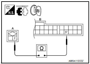
2 - 37: Continuity should exist.
3.CHECK IN-VEHICLE SENSOR
Check in-vehicle sensor.
4.CHECK CONTINUITY BETWEEN IN-VEHICLE SENSOR AND A/C AUTO AMP.
- Turn ignition switch OFF.
- Disconnect A/C auto amp. connector.
- Check continuity between in-vehicle sensor harness connector M34 (A) terminal 1 and A/C auto amp. harness connector M37 (B) terminal 36.
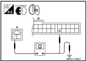
1 - 36: Continuity should exist.
- Check continuity between in-vehicle sensor harness connector M34 (A) terminal 1 and ground.
1 - Ground: Continuity should not exist.
Component Inspection
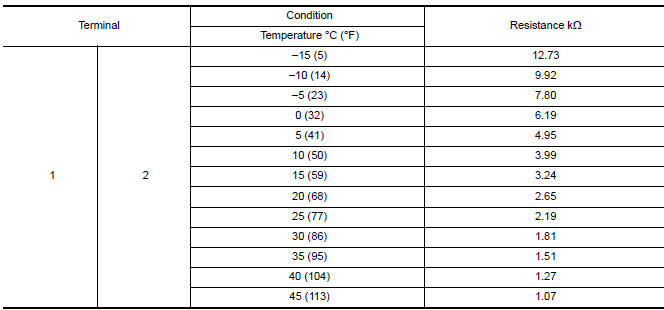
1.CHECK IN-VEHICLE SENSOR
- Turn ignition switch OFF.
- Disconnect in-vehicle sensor connector.
- Check resistance between in-vehicle sensor terminals.
 B257B, B257C ambient sensor
Description
COMPONENT DESCRIPTION
Ambient Sensor
The ambient sensor (1) is installed to the front bumper
reinforcement.
It detects ambient temperature and converts it into a resistance
va ...
 B2581, B2582 intake sensor
Description
Intake Sensor
The intake sensor is located on the evaporator.
It converts air temperature after it passes through the evaporator
into a resistance value which is then input to the ...
Other materials:
B1150 - B1153 side curtain air bag module LH
Description
DTC B1150 - B1153 LH SIDE CURTAIN AIR BAG MODULE
The LH side curtain air bag module is wired to the air bag diagnosis sensor
unit. The air bag diagnosis sensorunit will monitor for opens and shorts in
detected lines to the LH side curtain air bag module.
PART LOCATION
DTC Logic
...
Towing recommended by NISSAN
CAUTION
Never tow CVT models with the front
wheels on the ground or 4 wheels on
the ground (forward or backward), as
this may cause serious and expensive
damage to the transmission. If it is necessary
to tow the vehicle with the rear
wheels raised always use towing dollies
under the ...
Rear seat
Exploded View - Fixed Seatback
Headrest
Headrest holder (free)
Headrest holder (locked)
Bumper
Seatback assembly
Seatback trim
Seatback pad
Seat cushion trim
Seat cushion pad
Seat cushion wire cover
Seat cushion lock
Seat cushion assembly
Removal and Installati ...
Nissan Maxima Owners Manual
- Illustrated table of contents
- Safety-Seats, seat belts and supplemental restraint system
- Instruments and controls
- Pre-driving checks and adjustments
- Monitor, climate, audio, phone and voice recognition systems
- Starting and driving
- In case of emergency
- Appearance and care
- Do-it-yourself
- Maintenance and schedules
- Technical and consumer information
Nissan Maxima Service and Repair Manual

0.0084